Etukudo
Chain dimensioning provides a measurement standard for engineering and other technical drawings. It is common to refer to it as point-to-point dimensioning. In this article you will learn what chain dimensioning is, chain vs datum dimensioning, combined dimensioning, and how to perform it in popular software programs.
What is Chain Dimensioning?
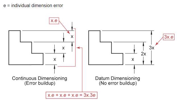
Chain dimensioning is a method of dimensioning from one feature to the next. Moreover, the dimensioning of each length proceeds from the end of the preceding one. Thus, every dimension depends on the previous one. When applying this method of dimensioning, the designer should be aware that the tolerance of each dimension builds on the next. As a result, there is tolerance buildup or stacking, which may lead to significant errors in fabrication. Despite this shortcoming, this method remains popular in design drawings. However, designers ofter complement it with another dimensioning method.
Chain Dimensioning vs Datum Dimensioning
Datum dimensioning is another method that enjoys wide adoption in the industry. Datum dimensioning overcomes the tolerance buildup shortcoming of the chain/continuous method. Nevertheless, it is often side-by-side with its chain counterpart in a design.
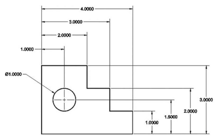
Differences between chain dimensioning vs. datum dimensioning are as follows:
| Chain Dimensioning | Datum Dimensioning |
| Dimensioning is done from point-to-point. | Measurements start from a common reference point. |
| Vulnerable to tolerance buildup. | Because all measurements are taken from a datum, it is not prone to tolerance buildup. |
| It properly defines a specific feature. | It does not define a specific feature, rather, measures the feature relative to a datum. |
| Because dimensioning is only on a straight line, it is easier to read. | Because dimensioning is parallel and solely from a datum, there could be errors during interpretation. |
Combined Dimensioning
Combined dimensioning refers to the use of both chain and datum methods on the same drawing. Moreover, it takes advantage of the strengths of each method and evades its shortcomings. As a result, it enjoys wide adoption in the industry.
How to Perform Dimensioning Using Software Programs
The following sections contain procedures for chain dimensioning using some popular software. Due to the evolution of computing systems over the years, computer-aided design (CAD) and computer-aided engineering (CAE) have become a mainstay in the engineering industry. Amongst several benefits, this software offer designers speed, flexibility, repeatability, and durability as long-term storage does not diminish the quality of projects.
Chain Dimensioning in Creo
Creo, from the developer PTC, is a family of CAD applications that supports product design for discrete manufacturing. As with its contemporaries, chain dimensioning on this software involves a few easy steps as follows:
- To begin with, click on Annotation > Annotate group. Then select ‘Linear’.
- Among the options under ‘Linear’, select ‘Chain’ to open the chain dimension dialog box.
- If applicable, select a tolerance type from ‘Tol type’ box and input the tolerance values.
- Else, click the first measurement point, then continue clicking subsequent points. Alternatively, after selecting the first point, include other points all at once using a box selection. If there is an error in selection, right-click and select ‘Back’ to remove the last point, then continue as normal.
- Under ‘Appearance’ modify parameters such as style, color, fill, and arrow appearance as per requirements.
- Select the position to locate the dimension text, then click the symbol to complete the operation.
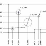
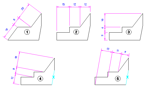
Following these steps can produce a range of dimensions in Creo which includes Parallel (1), Horizontal (2), Vertical (3), Para to (4), and Prep to (5).
AutoCAD Chain Dimensioning
AutoCAD, from the developer Autodesk, is the industry leader in CAD and drafting. Carrying out chain dimensioning on AutoCAD may vary slightly depending on the version, but follows this general procedure:
- After drafting the features, click the tabs Home > Dimension panel > Power Dimension.
- On the command prompt, enter ‘C’ to select ‘Chain’.
- Then, select a base dimension and an extension line origin where the measurements will begin.
- Use the settings on the ‘Power Dimensioning’ ribbon contextual tab to edit the features of the dimensioning such as text template, arrow style, etc.
- After that, specify subsequent points on the draft to dimension.
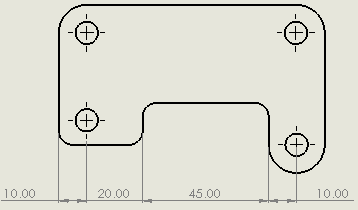
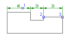
- Finally, press ‘ENTER’ twice to exit the dimension command, and the dimension will be complete as the figure below shows.
Solidworks Chain Dimensioning
Solidworks is a CAD and CAE software that uses parametric feature-based approach in solid modelling. Since its initial release in 1995 by developers Dassault Systèmes, it has enjoyed wide adoption. Performing chain dimensioning on Solidworks involves the following steps:
- First, choose the option by clicking Tools > Dimensions > Chain.
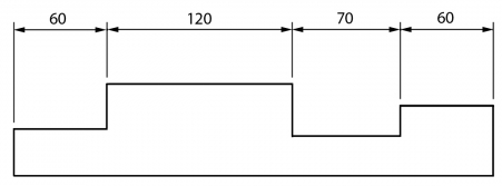
- Next, choose the starting edge on the object for the dimensioning as the figure below shows.
- Because the dimension type is a feature-based style, the subsequent step is to choose all features to add to the set. After doing this, the appropriate dimension appears for all the features selected.