Etukudo
An elevator hoist beam refers to a steel beam within an elevator machinery room that provides support to elevator equipment. Some of this equipment includes lifting motors, the elevator cab, and rails. In this article, you will learn about the application of an elevator hoist beam as well as beam sizing and design considerations.
Elevator Hoist Beam Application
During the installation of an elevator and ancillary equipment, some jurisdictions require the presence of a hoisting beam at the top of the shaft. When in use it provides support in the raising and lowering of components for the duration of the installation. Beyond the installation period, it serves as an anchor for personnel and equipment during repairs. Also, it is an attachment point for fall suppression devices.
According to design code, elevators shall have a means of halting upon exceeding design speed. Generally, at 10% above its design speed, the hoist motor shuts off. At 15% beyond the design speed, the elevator car safeties clamp on the guard rails, bringing it to a stop. Because these safety devices often anchor on the elevator hoist beam, they should be in place for the entire design life of the elevator.
Elevator Hoist Beam Sizing and Design
An elevator hoist beam, like every other beam, will be subject to bending stress, and to some extent shear stress. Thus, steel beams are the preferable choice of material. Although, engineers may choose reinforced concrete in certain applications. Because these hoist beams bear only static loads, their sizing and design are relatively straightforward.
Sizing of Beam
To properly size a steel elevator hoist beam, engineers follow these basic steps:
- Evaluate the load on the beam: The elevator installer must clearly define all loads that the hoist beam will bear throughout its lifespan. Since its loading is static, there should be a maximum load value (P) that represents the most onerous loading condition. Generally, these beams are rigidly supported at both ends as the diagram below shows.
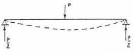
- Find the bending moment: Using the maximum load (P) and the length of the beam (L), the maximum bending moment (M) can be estimated using the following expression:
![\[ M=\frac{PL}{4} \]](https://punchlistzero.com/wp-content/ql-cache/quicklatex.com-390d73a06d6d47323ca4df0a843cabdf_l3.png "Rendered by QuickLaTeX.com")
- Estimate beam section modulus: First, select the grade of steel to use for the elevator hoist beam. Then, with the material’s allowable stress (σall), find the minimum required section modulus (S) as follows:
![\[ S=\frac{M}{\sigma_{all}} \]](https://punchlistzero.com/wp-content/ql-cache/quicklatex.com-9ccf4206c291401fae2b87b324d3e361_l3.png "Rendered by QuickLaTeX.com")
- Choose appropriate dimensions for the beam: Use the minimum required section modulus to estimate the dimensions of the beam. Moreover, the expression to determine these dimensions vary depending on the shape of the beam. For example, the following expression gives the requirements for the breadth (b) and height (h) of a rectangular beam:
![\[ S\leq \frac{bh^{2}}{6} \]](https://punchlistzero.com/wp-content/ql-cache/quicklatex.com-d1497a156192df8c5625f94a05427a26_l3.png "Rendered by QuickLaTeX.com")
After determining the minimum dimensions of the beam to prevent failure through bending, it is necessary to access if they also satisfy the shear stress requirements. Although, most times, failure occurs by bending, so the steps above should be sufficient to size the beam.
Design Considerations
In different regions, there are design regulations that govern elevator hoist beam applications. For example, in the USA, all structures of an elevator system must conform to the requirements of ASME 17.1. This safety code for elevators and escalators does not classify the hoist beam as a load-bearing structure after the installation of the elevator. Further highlighting the limited use of this component post-installation. However, as a support structure, the code specifies that it must be able to resist all forms of loading with a maximum deflection of 0.125 in (3 mm) at the point of support. Also, this beam shall be able to withstand simultaneous loading of all supported components in the event of an emergency. If applicable, loading should not exceed 27,500 psi (190 MPa). When it comes to the loading conditions, ASME 17.1 has different specifications depending on elevator usage, car frame and platform, and the load-bearing structure:
- Elevator usage: The code has requirements according to what a client is using an elevator for. For passenger and regular freight services, the code refers to these as Class A loading. While for automobile truck service and industrial truck service, they are Class B and Class C loading respectively.
- Car frame and platform: Structural analysis will vary depending on the type of car/cab frame as section 8.2 of the code highlights.
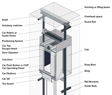
- Load-bearing structure: A defect could be a result of failure in any of the load-bearing structures when the elevator is in operation. According to the code, these include the guide rails, the car frame, the elevator platform, and suspension/hoist ropes.