General Arrangement (G/A) drawings present the overall composition of a plant, skid, building, or piece of equipment. In this article you will learn the process for generating a G/A, how to read a G/A, and using a G/A for document generation and equipment verification.
Generating a G/A
General arrangement (G/A) drawings are critical for viewing the overall configuration of a mechanical unit (e.g building, skid, plant, etc.) They also display an overview of key structural elements of a piece of equipment, structure, or assembly. Depending on the complexity of the object, G/As are likely to require a number of different projections, such as sections, plans and elevations. They may also be spread across several different drawings. G/As are generated when the following are required.
- Assembly drawings of process equipment (e.g. vessels, piping, valves, and instrumentation).
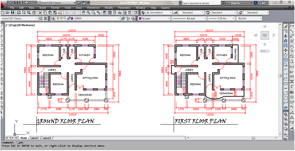
- Plan drawings (foundation, floor, deck layout and anchor bolt plans).
- Multiple views of one drawing, counting the entire model or a part of it.
- Erection elevation drawings.
- Information from model views, including 3D views.
Concept
The process of developing a G/A begins once the process flow diagram is complete and details of the P&ID are near completion. With the major processes determined, the engineer or designer develops a 3D model, which serves as the basis of the G/A drawings. The model is usually started by a designer before all detailed engineering calculations are performed, therefore the model and first-pass drawings are conceptual. In rare cases, the G/A is developed directly, without the use of a model.
General arrangement drawings provide accessibility and build options that are not build-ready but serve as a framework for further discussions with customers, engineers, fabricators, and other stakeholders. Plan and elevation views are typically provided, as well as a 3-dimensional isometric view. All drawings receive a title block that denotes key information such as project number, client, release date, drafter, and checker.
Model Review

A formal model review may take place, either with internal company stakeholders or external project stakeholders. This model review occurs prior to submitting the first revision of the G/As and may involve the customer, engineering firms (if applicable), quality and safety consultants, and any other stakeholders with a vested interest in the project. Model reviews for sophisticated assemblies take a component by component approach where each component’s integration, accessibility, and function is reviewed to ensure specification and governmental requirements are implemented.
Issued for Approval Drawings
As the design phase progresses, more information becomes available for the concerned structure (e.g geotechnical data, equipment datasheets, utility air design.) The model is updated with accurate weights and sizing, allowing detailed G/A drawings to be updated with the current information. In addition to the views already shown on the concept drawings, other views may be added. Drawings are typically labeled as alpha revisions at the stage, beginning with Revision A. Designated approval parties such as an engineering firm or end customer reviews these drawings. G/A drawings are either returned as “Approved”, “Approved with Comments”, or “Revise and Resubmit”, typically within a two week time period. For fast track projects, this phase may compress into a single joint working session.
Detailed Design and Release
The model review and stakeholder commentary inform the final G/A drawing pickups. By this point, all engineering information, customer specification, and stakeholder input exist in the model and subsequently the G/A. Revision of the G/A drawings per stakeholder comments allow for construction-ready G/A drawings. The designer appends tables, drawing notes, and customer specification references to ensure build suitability. Drawings with numeric revisions at this stage, beginning with Revision 0, go to the shop, customer, or a qualified subcontractor so construction may begin.
G/A Standards and Requirements
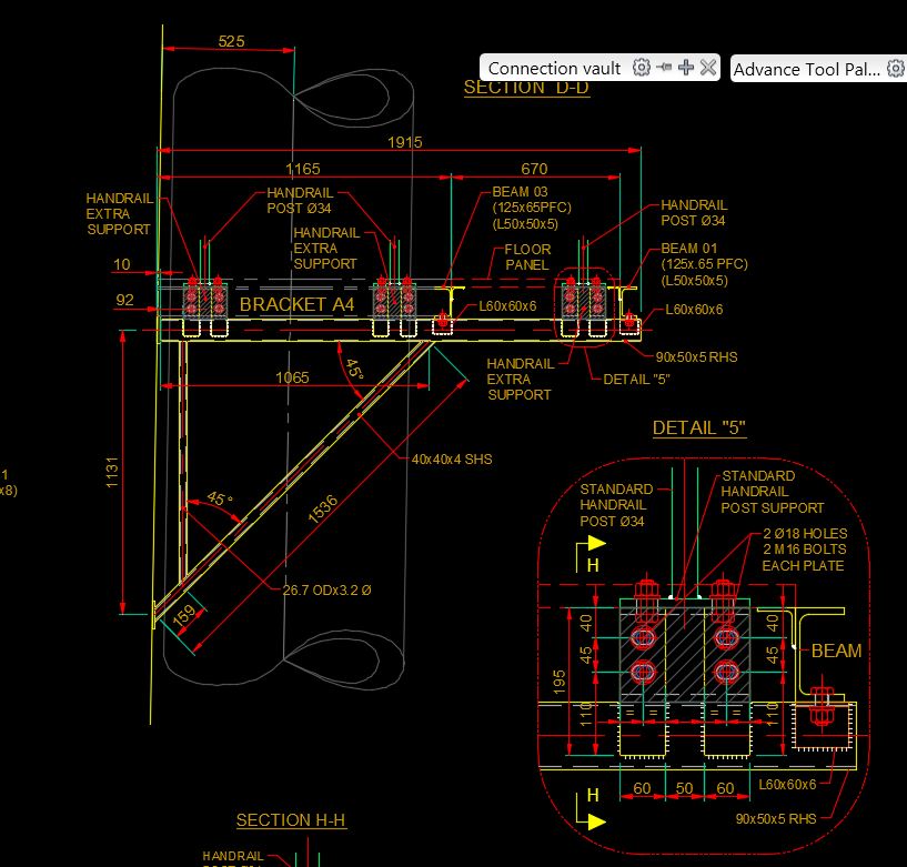
G/A’s usually require additional detailed drawings that show specific elements of the assemblies and construction details. Very simple projects may already include these features on the G/A themselves, but usually, separate drawings must be generated. Examples of additional detail drawings are structural skid drawings and piping isometrics.
Symbols and notations consistent with industry standards allow for clear understanding by all stakeholders. The drawing’s scale reflects the level of detail of the information conveyed (e.g floor plan’s scale reflects 1:50, or 1/4”=1′-0”). G/A drawings typically contain build notes for information that is difficult to express dimensionally.
How to Read a G/A
Two types of views appear in a 2D drawing: orthographic (plans and elevations) and pictorial (isometric). Orthographic views dominate G/A drawings, whereas isometric views provide build context and typically lack dimensions.
Reading a G/A drawing is straightforward. A multitude of 2D, dimensioned orthographic views, allow users to comprehend construction details.
Using a G/A
Engineers utilize G/A drawings for equipment verification, orientation and integration, and document generation.
Verification
From a G/A, overall dimensions, the orientation of individual components, weights, accessibility, and build suitability are verified. Validation of the overall dimensions and orientation of components (e.g clearances, handrails, platforms) ensures the proper and appropriate installation of the mechanical unit. Assembly weight is validated to ensure proper loading and support structure is accounted for.
Orientation & Integration
The G/A depicts the location and assembly of all components within the system. In cases of issues or broken parts, G/A drawings can be utilized to pinpoint and repair the specific component that causes the obstruction. G/As also allow for additional documents to be generated.
A unit typically integrates around and adjacent to an existing or planned process. As such, only certain dimensions/locations allow the process to run properly. When the designed plant, skid, building, or piece of equipment reaches site, the G/A drawing in conjunction with installation instructions allows the end-user/contractor to properly integrate the system.
Build
G/As govern the build process to ensure heights, overall dimensions, and equipment locations are appropriate. The G/A is one of the key drawings that the shop floor will use to locate, validate, and understand equipment integration. Strict, internal control of the G/A prevents duplicate revisions on the shop floor. During the build process, it is common for the shop to find issues or optimization opportunities with the G/A drawings. An internal redline process allows qualified personnel to mark up the drawing, provide their signature, and allow construction to continue. When significant changes are required to the drawings, it is recommended a new set of G/As is released from the engineering/design department.