Etukudo
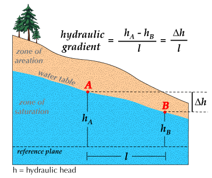
Hydraulic gradient refers to the change in water level per unit distance along the direction of maximum head decrease. Simply put, it is the rate of change in total head per unit distance of flow in a particular direction.
In this article, you will learn the implication of hydraulic gradient, its formula, the use of critical gradient, and applications to engineering and design.
Implication of Hydraulic Gradient
Inherently, hydraulic gradient is a vector gradient, as it relates to multiple hydraulic head measurements along a flow path. Naturally, water flows from a region of higher head to that of a lower head. As a result, the greater the difference in total head, the higher the propensity to flow. Thus, this highlights the importance of hydraulic gradient in flow systems.
It also describes the effectiveness of the driving force behind water movement. In addition, for groundwater, hydraulic gradient is also referred to as Darcy’s slope because it determines the quantity of a discharge or Darcy flux through the soil or any porous medium. Hence, it is an important concept, forming the basis of hydrogeology.
Hydraulic Gradient Formula
Calculating the hydraulic gradient between two points involves finding the head at the origin (h1), and the head at a point of interest (h2). Computing the ratio of the difference between the two heads as well as the distance between them (ΔL) in the flow direction produces the hydraulic gradient (i).
![\[ i=\frac{h_{2}-h_{1}}{\triangle L} \]](https://punchlistzero.com/wp-content/ql-cache/quicklatex.com-41b0c2f2c353b57c66731bdb06cf59ce_l3.png "Rendered by QuickLaTeX.com")
Because flow goes from a higher head to a lower head, h1 is higher than h2, thus, the value of the hydraulic gradient is always negative. Also, in complex scenarios, where flow is not aligned in a particular axis (x, y, or z), the expression of the hydraulic head field in all three dimensions is as follows:
![\[ \triangledown h=\frac{\partial h}{\partial x}i+\frac{\partial h}{\partial y}j+\frac{\partial h}{\partial z}k \]](https://punchlistzero.com/wp-content/ql-cache/quicklatex.com-4b36d6cc28210b8641dd96b92b38905a_l3.png "Rendered by QuickLaTeX.com")
This vector quantity can then be used to describe the direction of flow.
Use of Critical Hydraulic Gradient
Critical hydraulic gradient refers to the hydraulic gradient value at which particles start to flow out of a soil sample. Moreover, at this value, the gradient is so high that seepage exits alongside soil particles from the area. As a result, floatation of particles occurs. To determine the critical hydraulic gradient (ic), calculate the ratio of the soil’s submerged unit weight (γsub), to the unit weight of water (γw). Furthermore, the sample’s submerged weight is the difference between it’s total unit weight (γ), and the unit weight of water (γw).
![\[ i_{c}=\frac{\gamma -\gamma _{w}}{\gamma _{w}}=\frac{\gamma _{sub}}{\gamma _{w}} \]](https://punchlistzero.com/wp-content/ql-cache/quicklatex.com-3fd8122e0962b57a209fe376e1249422_l3.png "Rendered by QuickLaTeX.com")
In addition, the critical hydraulic gradient can also be calculated using the specific gravity of the soil (SGs) and its void ratio (e).
![\[ i_{c}=\frac{SG_{s}-1}{1-e} \]](https://punchlistzero.com/wp-content/ql-cache/quicklatex.com-583063c8e7c1be23b7cb6a699d6edfe6_l3.png "Rendered by QuickLaTeX.com")
After finding the critical hydraulic gradient of soil, it can serve to characterize the seepage stability of the sample, relating to its density and porosity. Therefore, insights can be obtained regarding the occurrence of internal erosion of soil, thus, predicting the response of a sample as conditions change. Also, scientists use the value of the critical gradient to infer other important soil parameters such as interface roughness, degree of compaction, clay content, etc. This is only possible after carrying out significant laboratory testing on the sample.
Applications to Engineering and Design
The concept of hydraulic gradient is important in science and engineering, especially when dealing with systems that interface with the soil.
Groundwater Systems
Generally, to simplify analysis, the assumption that groundwater systems are in a steady-state is common. However, a transient condition depicts a true representation of such systems over time. For example, take two groundwater reservoir systems as the diagram below highlights.
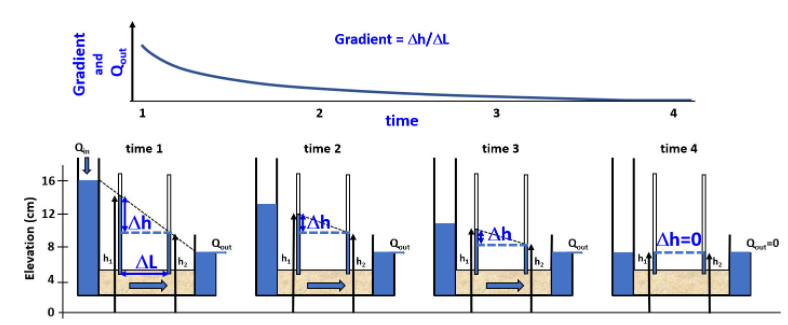
In the first instance, the reservoir on the left has flow coming into it while that on the right is flowing out. Because of the difference in head between the two reservoirs, a hydraulic gradient exists which causes flow from the left to the right reservoir. At time t2 the inflow to the left reservoir stops, but outflow continues from the reservoir on the right, thus diminishing their difference in head. Eventually, this difference erodes completely, with the system becoming static when the heads are equal. Understanding that groundwater systems are constantly in a state of flux due to hydraulic gradient is pivotal in system design. In addition, it also has importance in open-channel flow. In such systems, it can serve to determine whether a tranche is gaining or losing energy.
Water Pumping Systems
The concept of hydraulic gradient is also important in setting up water pumping systems, especially when deploying multiple pumps. In such systems, pumps connect in parallel to achieve an increase in flow rate. Increase in pressure occurs by connecting multiple pumps in series. Before deploying the pumps, having a hydraulic gradient profile of the entire system is a prerequisite. This helps to understand how the gradient varies and thus allows for appropriate pump location. Also, it provides designers with the minimum head each pump should have. In addition, the rating of the pipes in the system can be estimated.
Darcy’s Law
Darcy’s law describes the one-dimensional movement of water through soil under saturated conditions. The law estimates the water flux (J), as a product of the soil’s hydraulic conductivity (K), and the hydraulic gradient (i).
![\[ J=-Ki \]](https://punchlistzero.com/wp-content/ql-cache/quicklatex.com-cd71319c47a635ac548148ae8deab0a3_l3.png "Rendered by QuickLaTeX.com")
The minus sign before the conductivity keeps its value positive and maintains directional integrity.