Instrumentation is the collective term for instruments that are used for indicating, measuring, and recording physical quantities in systems. Instrumentation gives engineers and operators insight into system behavior and allows for safe and efficient operation. In this article, you will learn about instrumentation types, functions, applications, construction, and repair and maintenance considerations.
Instrumentation Types
There are two main categories for instrumentation types: local and system.
Local
Local instrumentation is not connected to a large logic system and is simple in nature. Local instrumentation is often used as a fault detector and an indicator for readings on the floor. Examples include temperature dial indicators, pressure dial indicators, and level gauges.
System
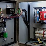
System instrumentation refers to instruments connected to a larger logic system. System instrumentation may be used in lieu of local instruments, or in addition to local instruments. Instruments in this system are connected together and are often input signals for valves, pumps and actuators to modify outputs. For example, if a level sensor determines a tank’s level is too high, it sends a signal to a drain valve to lower the level. The two most common types of system instrumentation are 4-20 mA current loop instrumentation and the fieldbus instrumentation.
4-20 mA Current Loop
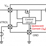
In the 4-20 mA current loop system, a physical reading is converted into a current source between 4 and 20 mA in a simple circuit. The lowest possible reading of the instrument is assigned a 4 mA signal and the highest possible reading is assigned a 20 mA signal. Going back to the tank example, if the tank is empty, the sensor will send a 4 mA signal, if it’s full, it’ll send a 20 mA signal, and if it’s half full, it’ll send a 12 mA signal. This system is helpful for detecting sensor faults as faults are indicated by sending a signal less than 4 mA or more than 20 mA.
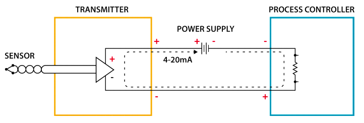
Current loops are cheap to build, simple in design and can easily detect errors. This makes 4-20 current loops a very popular system in small systems of instrumentation. However, there is a major drawback in current loop systems when the number of instruments increases. That drawback is that in a current loop, each instrument requires its own pair of wires in order to function properly. If the loops are not properly installed, ground loops become a problem and require some loops to be isolated. These isolation requirements become exponentially more complex as more loops are added and limit the number of instruments a 4-20 system can have.
Fieldbus
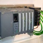
In a fieldbus instrumentation system, individually powered I/O Data Blocks connect to instruments. A programmable logic controller connects to each individual I/O Data block, allowing lots of data transfer with minimum wiring. The use of multiple data blocks per single controller allows for a larger instrument capacity. Multiple programmable logic controllers may be used to increase capacity or reduce controller load. These controllers can then be connected to each other with computers, creating a hierarchy system. In this hierarchical system, instruments can communicate with each other while also receiving instructions from the computer or computers.
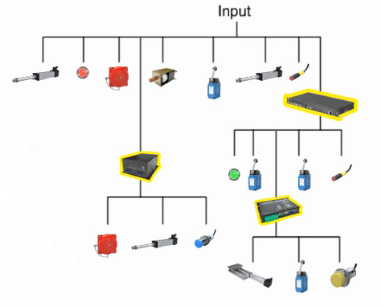
Fieldbus systems can be scaled larger and provide robust communication. This makes fieldbus systems common in large plants and facilities. However, due to their expense and complexity, they are appropriate only for large installations.
Function and Application
Choosing the proper instrument starts with determining what is needed, where it is needed, and the desired operating range. Here we will discuss how sensors detect physical attributes.
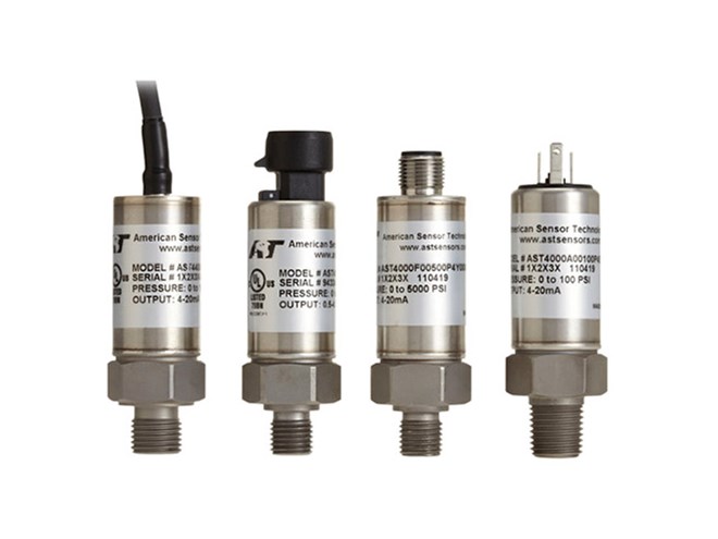
Pressure Sensors
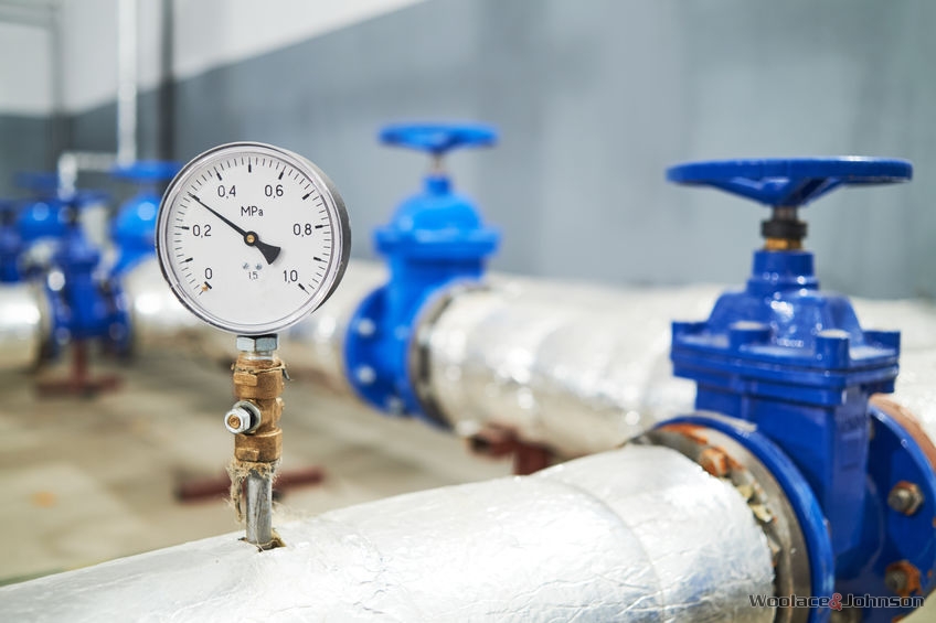
Local or dual local/system applications use a pressure gauge that converts pressure into mechanical energy. The mechanical energy pushes a dial indicator and delivers a read-out.
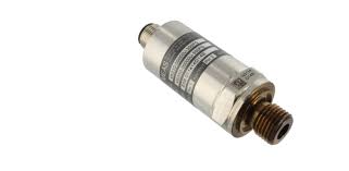
System applications use pressure transmitters that measure force on a small area on the sensor. That force is converted into electrical data that is delivered to the instrumentation logic system. In many industrial applications, pressure transmitters are often connected to release valves. The transmitters act as a trigger to open and shut valves in order to keep the pressure in the desired range.
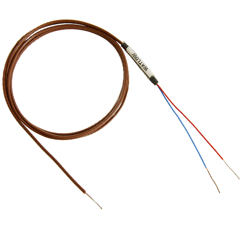
Temperature Sensors
Local or dual local/system applications use a temperature gauge that has a sealed capillary tube and bulb assembly that is filled with temperature-sensitive liquid. As the temperature changes, the pressure changes and moves the gauge’s pointer.
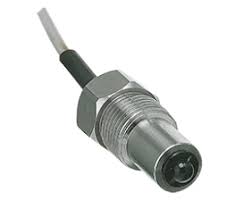
Temperature transmitters measure the temperature of its surroundings and convert that into an electrical signal. The most common types of temperature transmitters are thermistors and thermocouples. Thermistors use temperature-sensitive resistors to produce an electrical signal. Thermistors highly accurate but have heat limits. Thermocouples have two wires made from different wires to form a junction. This allows thermocouples to withstand higher temperatures. Temperature sensors are commonly used where a prescribed amount of heat is to be delivered to modify a process media. They often act as triggers for burner control and stability.
Liquid Level Sensors
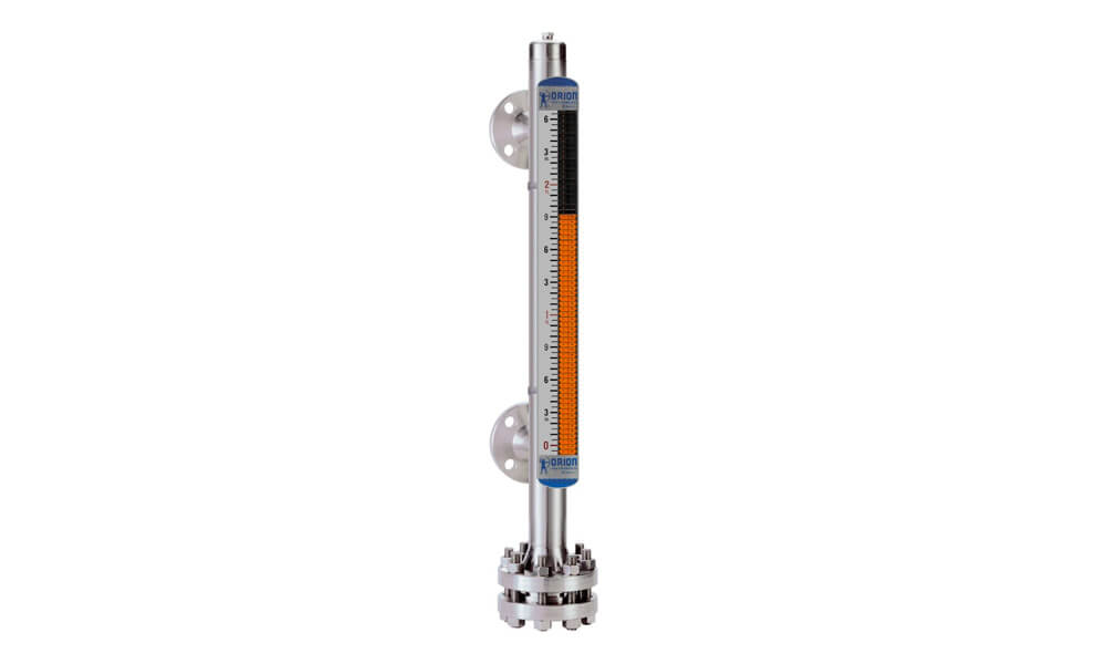
Local or dual local/system applications may use a magnetic level gauge to provide a level read-out. A level indicator is attached to the vessel that requires monitoring. A float with a magnetic assembly rests on the fluid’s surface. As the fluid rises, the magnet assembly rotates a series of colored flaps to display the fluid’s level.
Liquid level transmitters detect the water level in a tank or container. The type of sensor is dependent on the type of liquid that is used. If the liquid is conductive, then the transmitters can be an open circuit at the desired level. The liquid then acts as a switch, closing the circuit when it reaches the desired level. If the liquid is not conductive, the sensor may be placed at the top of the container and measure the distance to the surface of the liquid.
Other Common Sensors
There are many other types of sensors that can help monitor and control a system. Corrosion sensors detect wall thickness erosion and whether a vital pipe or valve needs replacement. Vibration sensors detect acceleration and whether the process is in the proper range. PH sensors determine whether a subject fluid is acidic or basic. Other specialty sensors may be required based on a system’s operating parameters and the required control mechanism.
Construction and Materials
When installing an instrumentation system several key features need to be considered. It needs to be determined which sensors shall be deployed, the desired range, and how connections will be made. Sensor material is dependent on the process media, environment, and project specifications. Below are the most common materials for sensors.
Stainless Steel
Sensors are commonly made of stainless steel, due to its balance of strength and cost-effectiveness. The most common types of stainless steel used for pressure sensors is 17-4 PH and 316L stainless steel. 17-4 PH is typically stronger than 316L and therefore makes it a good candidate in spring materials. In corrosive materials however, 316L is more common due to its corrosion resistance. Both materials are fairly economical. For level sensors, stainless steel construction is common for high temperature, and high pressure environments.
Metal Oxides
Various metal oxides are common in thermistors. These metal oxides include magnesium oxide, nickel oxide, cobalt oxide and copper oxide. These materials allow thermistors to survive extremely high temperatures.
Testing, Repair, and Maintenance
Each individual instrument is subject to rigorous quality inspection prior to integration into a logic system. Upon integration to a system, testing usually includes a factory acceptance and site acceptance test. Loop, logic, and visual checks are part of the commissioning process for a new instrumentation system.
It is important to make ensure sensors are functioning properly at all times. In a 4-20 system, faults are detected easily via a code outside of the normal operating range. In a fieldbus system, a fault detection system can be coded to the system to make sure each sensor is functioning properly and indicating those that are having faults.
During operation, the instrumentation is typically inspected and replaced on a break-fix basis. Parts with mechanically moving parts or subject to excessive direct contact with process media may require replacement or refurbishment on a more frequent basis. In such a case, the manufacturer of the individual instrument sets the guidelines and expectations for maintenance and replacement.