Etukudo
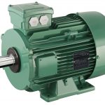
A motor peckerhead is an electrician’s slang referring to the wiring box that is mounted on an electric motor. In professional language, it has a host of names including the terminal box, junction box, and connection box.
In this article, you will learn the purpose of a motor peckerhead, some design requirements, the various mounting orientations, and its wiring and connections.
Purpose of a Motor Peckerhead
Electric motors, especially those of higher horsepower for industrial purposes, have terminal boxes. Technicians casually refer to these boxes as peckerheads. Moreover, these peckerheads, serve as a connection point between lead wires from the motor, and feed wires from the electrical power source. In addition, the terminal box offers protection to both the client’s device and motor body by connecting the wiring to a ground. Generally, the size and material of a peckerhead is representative of the voltage grade of the motor. Meaning that the higher the voltage of the motor, the larger the volume of the terminal box. Thus, it is possible to qualitatively determine the voltage grade of a motor from its connection box.
Basic Design Requirements of a Motor Peckerhead
Despite the simple function of a motor peckerhead, there are basic requirements depending on the motor voltage grade, and other of its specifications. A couple of these requirements that ensure the safety of the equipment are the electrical gap and creeping distance.
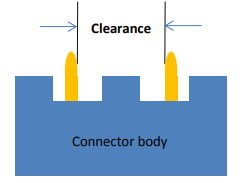
Electrical Gap
An electrical gap refers to the clearance between two electrical conductors through the air. Moreover, this clearance will determine how much voltage will cause an arc between the two conductors. So, as the working voltage and nominal AC mains voltage increase, there is a corresponding increase in the electrical gap between conductors in the peckerhead. As a result, the volume of the terminal box gets bigger with increasing voltage. This ensures the safety of the conductors and other equipment. In addition, other factors that influence the electrical gap of conductors in a peckerhead are the type of insulation and the pollution degree. Considering these factors, Table 2H of IEC 60950 provides guidance on how to calculate this clearance.
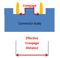
Creeping Distance
Creeping distance or creepage refers to the total linear distance along all the insulating surfaces between two electrical conductors. Moreover, since it is the total surface distance between the conductors and not just the air gap, it is considerably longer than the electrical gap. However, its value is largely a function of the electrical gap as the following explanation highlights. When an electric arc occurs over an insulating surface, there is often some carbon trace left behind on the surface. As a result, there is a reduction in the isolation of the conductors and an increase in the leakage current. Because carbon is more electrically conductive in comparison to insulation material. Furthermore, this shortens the equivalent electrical length, making the motor peckerhead conductors more susceptible to subsequent arcing.
Peckerhead Mounting Orientation
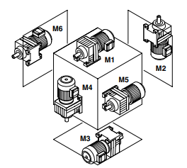
A motor peckerhead can take up a variety of mounting positions. These could be 0°, 90°, 180°, or 270°, from the perspective of the output shaft or fan guard. Also, the cable entry into the terminal box can be of positions “1”, “2”, “3”, or “X”, which is the standard position, as seen in the diagram below.
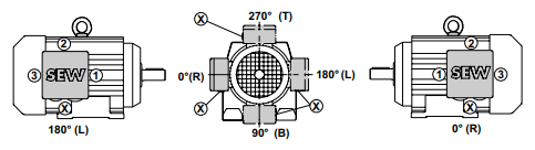
The position of the terminal box depends on which orientation the motor is mounted. The cable entry point is a function of the terminal box position, especially in gear motors. Each manufacturer has specifications concerning cable entry points and peckerhead orientations, so it is necessary for the client to be in contact in view of any changes.
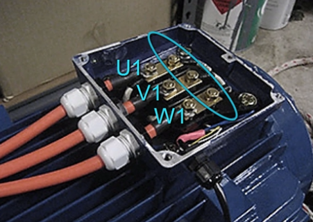
Peckerhead Wiring and Connections
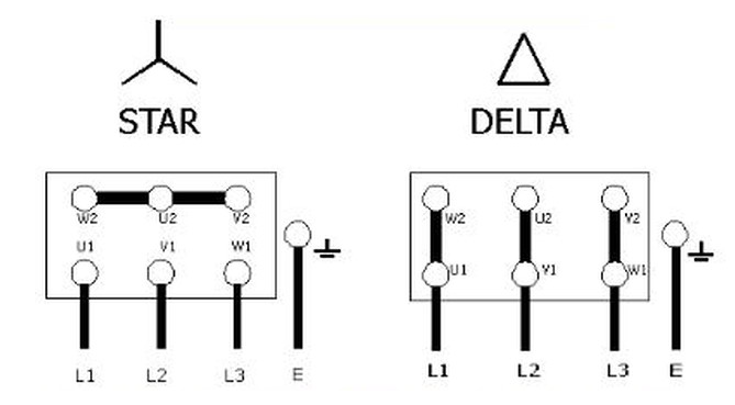
The wiring system within the peckerhead is pivotal to the way the motor functions. Typically, when starting a motor, the current has to be several times more than the motor current rating. As a result, the electrical network experiences higher levels of stress at startup. However, as the motor rotation speed increases, the starting current reduces to the stated motor current. To avoid this high starting current, the use of star-delta connections is on the increase as the starting method, especially for asynchronous squirrel-cage motors of greater power (above 4 kW).
When it comes to the termination options for the wire connections in a motor peckerhead, the common ones include:
- Tab Connections: These enable the removal and insertion of wires quickly without any need for soldering.
- Screw Clamps: For this termination, an electrician uses a screw to tighten the wire while making the connection. They are the standard type in the industry. Because they are suitable for a wide range of wire sizes and are reliable.
- Spring Clamps: In this type of termination, the force of a spring retains the wire in place. Particularly, they are useful for wires of small diameters and in applications with limited spacing.
- Insulation Displacement Connections: These connections entail pushing a wire between two sharp pieces of metal. Thus, making a connection without exposing any bare wire within the peckerhead.