Etukudo
A pipeline header connects flowlines from several different sources into a single gathering line. In this article, you will learn the purpose of a pipeline header, important factors in its design, and calculation methodology.
Pipeline Header Purpose
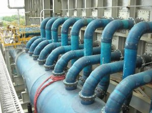
A pipeline header refers to a large pipe that is set up to aggregate flow from smaller pipes (collecting header). On the other hand, it can also distribute flow to many smaller pipes (distributing header). Typically, the design of flow systems with headers is due to a variety of reasons.
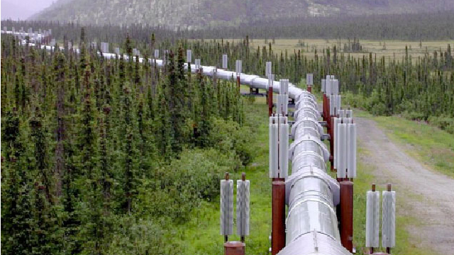
- Production and Distribution: In the oil and gas industry, headers serve to commingle flow from different wellheads into a single production pipe. As a result, an exploration company can achieve significant savings on pipeline infrastructure. This holds especially true in oil fields where the wells are widely distributed and some distance away from the processing facility. In addition, the headers serve as a means of distributing fluids that mitigate corrosion and hydrate formation to various sections of the piping system.
- Testing and Metering: In some applications, headers have testing and metering valves that direct fluids into testing vessels. Using this, operators can determine important flow details such as production rates and gas/liquid ratios.
- Exhaust Systems: Pipeline headers are common deployments for taking exhaust fumes out of engines. Moreover, their presence is necessary especially when aggregating fumes from multiple combustion chambers. As a result, engines can deliver measurably better horsepower, torque, and mileage.
Pipeline Header Design
The design of a pipeline header largely depends on its application. As its use varies, so does the design approach. However, there are some considerations that apply no matter the scenario.
Pressure
In a distributing header, as flow branches out, there is a corresponding pressure drop depending on the line size and flow rate of the branch. Thus, the last branch outlet on such a header is likely to have the least available pressure to drive flow. Therefore, the design engineer must ensure that the supply pressure is adequate to meet all flow requirements in each branch.
On the other hand, for a collecting header, different sources flowing into a single header at diverse pressures also pose a challenge. Without proper design, a high-pressure branch could cause backflow into a lower pressure branch. The use of chokes and valve help mitigate this risk. In addition, there are pressure drops due to the presence of bends and tees on the header. All these elements require consideration when designing a header.
Flow Rate
To satisfy the production requirements in a facility, flow rates for each line must meet a set value or within a limit. Also, in drainage applications, professionals set a threshold flow rate to avoid hold up at drains. The flow rate value highly depends on the supply pressure and line sizes, and thus requires proper consideration. As a result, valves and chokes provide isolation and metering on headers to satisfy the needs of the application.
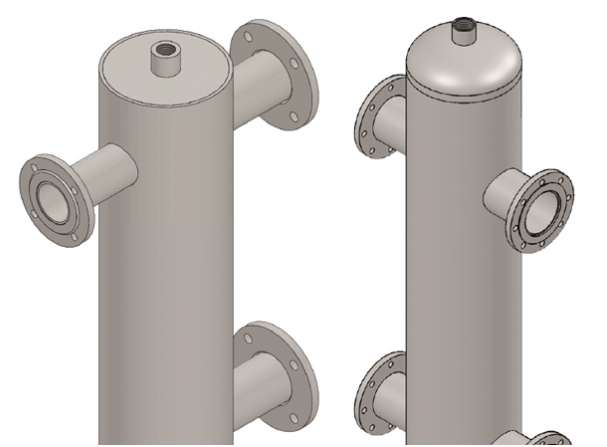
Header-Branch Arrangement
Typically, piping designers set branches parallel to each other and connect them to the horizontal header pipe. However, with varying needs such as in separation applications, a header could be vertical. In addition, for distribution headers, if branch pipes differ in diameter, then their location relative to the header inlet affects the pressure and flow rate in each branch. Moreover, the pipeline engineer needs to locate each branch carefully to meet the flow specifications in each branch.
Temperature and Mechanical Strength Requirements
Beyond the flow requirements, a pipeline header design should meet temperature and mechanical strength requirements. Depending on the fluid temperature, the header will be subject to varying levels of thermal stress. This holds especially true in collecting headers where the fluid originates from different sources. In addition, the type of connection at each branch determines the need for reinforcement. ANSI/ASME B31.3 provides guidance on the use of reinforcements.
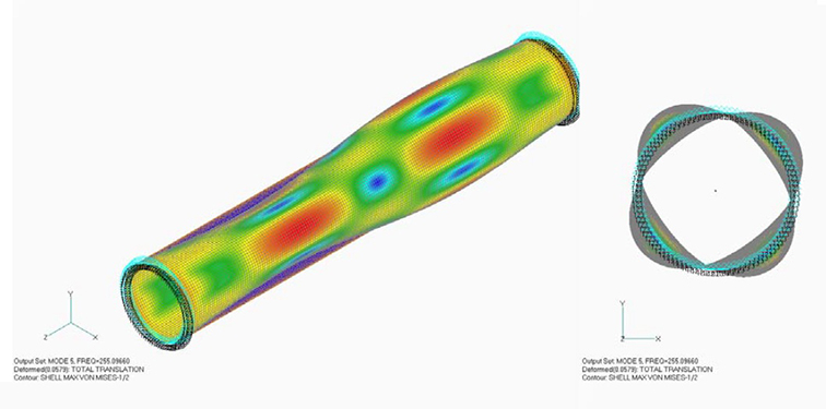
Pipeline Header Design Calculation
In practice, calculating the design parameters for a pipeline header often involves the use of computer simulations. Finite Element Analysis (FEA) provides a tool for engineers to analyze a header’s mechanical and thermal stresses. The results from these stress analysis simulations helps identify the suitable pipe material and the need for any other apparatus. For example, if the thermal stresses would be excessive for a header to bear, cooling spools could be integrated into the header design.
Similarly, Computational Fluid Dynamics provides a means for evaluating the flow requirements. Using different line sizes, engineers can determine the pressure and flow rates in the header and various branches. Also, this tool permits the evaluation of a variety of flow scenarios to ensure the design is robust enough.
Nevertheless, there are less sophisticated approaches that engineers can follow in designing a pipeline header. As a preliminary step, Bernoulli’s equation provides indications of design feasibility. This equation relates the pressure upstream (P1), the flow velocity upstream (v1), and upstream elevation (z1), to their downstream equivalents. In addition, Bernoulli’s equation accounts for head losses due to friction (hf) and minor losses due to pipe fittings (hm).
![\[ \frac{P_{1}}{\rho g}+\frac{v_{1}^{2}}{2g}+z_{1}=\frac{P_{2}}{\rho g}+\frac{v_{2}^{2}}{2g}+z_{2}+h_{f}+\sum h_{m} \]](https://punchlistzero.com/wp-content/ql-cache/quicklatex.com-98abbf8c8275a59c224da196c59edfb4_l3.png "Rendered by QuickLaTeX.com")
Calculation Methodology
Using Bernoulli’s equation, here is a methodology that can evaluate the pressure requirements for a distribution header for three users with the following specifications:
- First User: 20 GPM.
- Second User: 10 GPM.
- Third User: 5 GPM at the end of the main header.
Step 1
Assuming all users discharge at atmospheric pressure, pick line sizes for the two branches (first and second user) and the pipeline header.
Step 2
Calculate the pressure drop between the third user discharge (5 GPM) and where it joins the second user. Similarly, calculate the pressure drop between the second user discharge (10 GPM) and where it joins the third user. Take the higher of these pressure values and call it pressure ‘A’.
Step 3
Using a combination of flow from the second and third users (15 GPM), calculate the pressure drop from the second user take off to the first user take off. Add this value to pressure ‘A’ and call it pressure ‘B’.
Step 4
Now, calculate the pressure drop from the first user discharge (20 GPM) to where it joins the second and third users. Then, compare this value to pressure ‘B’, and adopt the higher one as pressure ‘C’.
Step 5
Finally, calculate the pressure drop for all three flows (35 GPM) from the first user’s take-off to the supply source, perhaps a pump. Add this value to pressure ‘C’ to give you the supply pressure the pump or whatever source needs to operate at. If this pressure value is not achievable, then adjust the line sizes and recalculate the pressure values.
These are useful preliminary steps that can reveal the feasibility of a header design on the basis of its flow parameters. If these basic calculations show that the design is feasible, then further investigations using CFD and FEA simulations are a requirement before fabrication in most cases.