Programmable Logic Controllers (PLC) are industrial computers that have been adapted to run industrial and manufacturing processes. They are the brains of industrial process, giving orders and passing information to machines and instruments. In this article, you will learn the components of PLCs, their functions, construction, and repair and maintenance.
Components
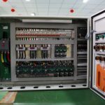
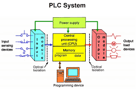
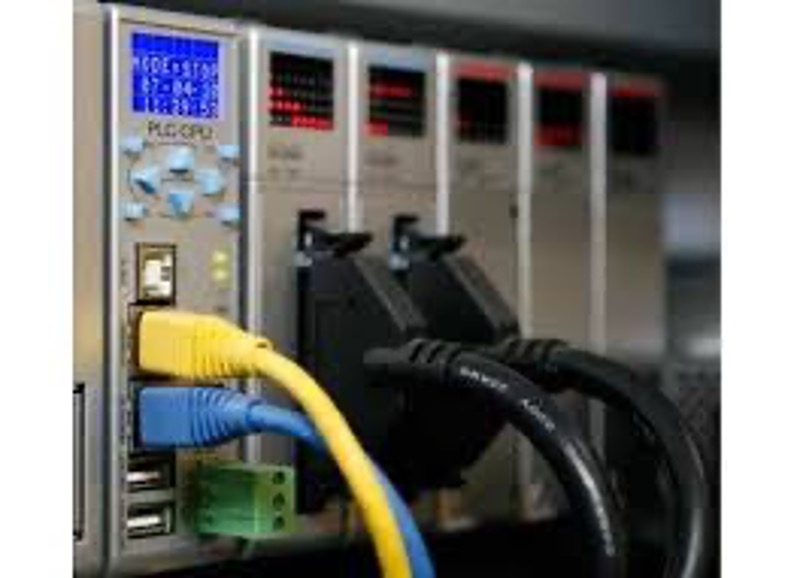
PLCs are responsible for logical decision making in the industrial process. They are lightweight, rugged devices that perform tasks that formerly required relays, solid state electronics, and mini computers. PLCs have 4 main components that allow PLCs to make proper logical decisions. Those components are input/output modules, power supply, processor, and programming unit.
Input/Output Modules
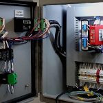
PLCs are sensitive to electrical noise from its inputs and outputs. Noise can give the PLC inaccurate information from which it can make an incorrect decision. Therefore, I/O modules are used to filter signals and validate voltage levels so that the PLC can make proper decisions with accurate data. Inputs to the PLC range from push buttons to levers to sensor readings and other devices and instrumentation. The input module filters and sends the signals to the processor for decoding. Then the processor sends signals back to the output modules. The output module translates the signal to a voltage (AC or DC), filters the noise out, and sends the desired signal to output loads such as motors, solenoids, lights, indicators, and contactors.
Power Supply
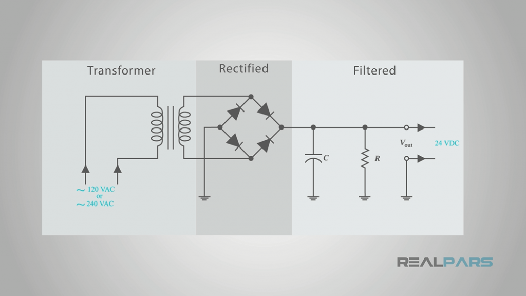
The power supply is an essential component of the PLC. First, it converts a 120 V or a 240 V AC power signal into a typically 24 V DC signal. The resulting DC voltage powers the rest of the PLC and its components. The components then can use the signal as a reference current to send signals to outputs or different components in the system. Usually, the reference current is between 2 and 10 A in smaller systems and can exceed 50 A in larger systems. Most PLCs also have a backup battery to provide power to the PLC’s memory in the event of a power supply failure or a power outage in general.
Processor
The processor is the brain of the PLC. Similar to a computer processor, the PLC processor takes in the inputs from the input modules. Then the processor performs the instructions given to it by the program using the input values. Finally the processor sends signals to the output of the operation. For example, a button is pressed to signal the start of a pump. Therefore, the processor signals the start of the pump. Per the programming instructions, the pump is to stop once the level of the fluid reaches a desired point. Once the liquid reaches the point, the processor signals the pump to stop. The processor constantly takes in inputs and running them through the program and sending the output to the desired output or in memory.
Programming a PLC Unit
PLCs are commonly programmed from a P&ID and cause and effect sheet. The P&ID shows all major components in a system and its order of operation. The cause and effect sheet lays out the input-output logic for various components (i.e. a temperature high-high alarm triggers a shut-down switch).
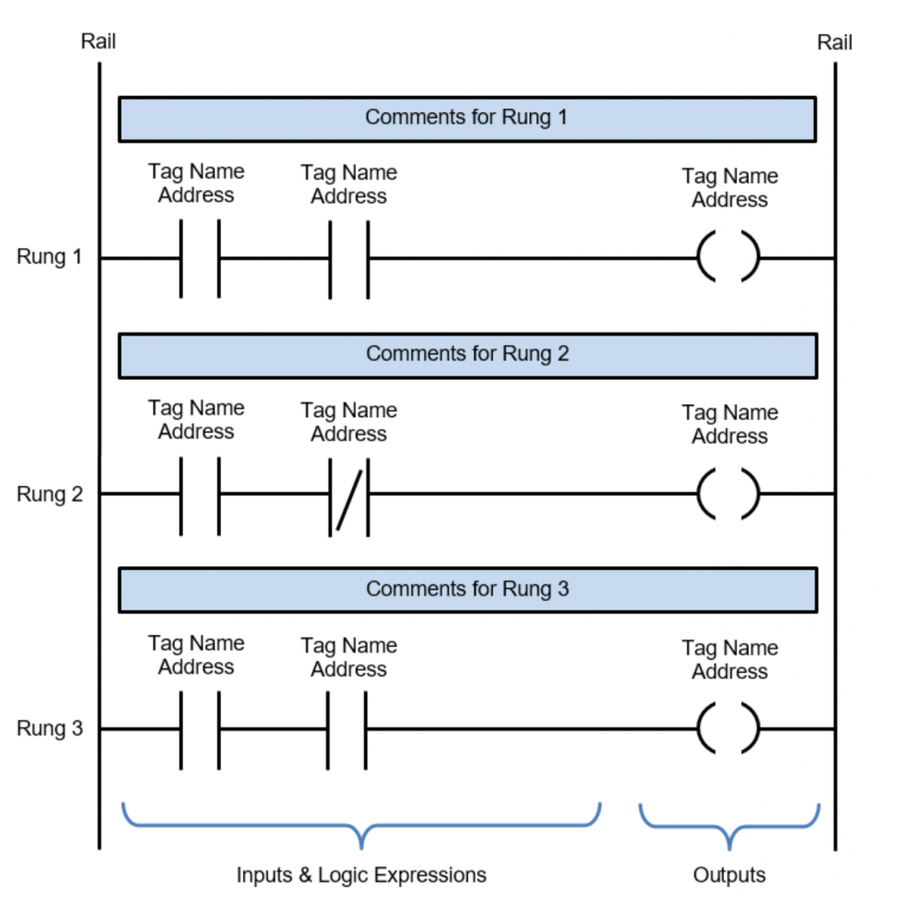
The cause and effect sheet and P&ID serves a the ladder logic. Ladder logic allows the programmer to visually see the network. Ladder logic is a simple way to code, requiring little training for the programmer. Programs determine the desired ranges for processes and write instructions for the PLC. They are often the guide for the PLC. The instructions are stored in the PLC’s memory.
Functions and Applications
PLCs are responsible for controlling and maintaining the steps in the process and ensure that the proper steps are taken. PLCs continuously monitor input values and takes the necessary action on them. They are the metaphorical composer of the industrial system. PLCs constantly ensure the proper steps are taken in the process, that the right motors are activating at the right speed, at the right time for the right duration.
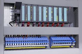
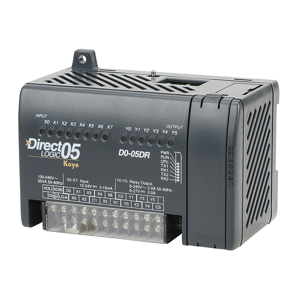
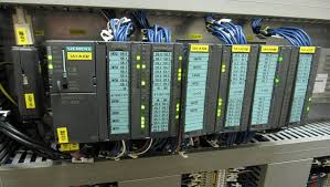
PLC types vary based on the application. The first application is the unitary PLC. Unitary PLCs store all the basic components listed above in a single compartment or box. They are the simplest application of PLC. Operations with fewer inputs and outputs use unitary PLCs. The next application is modular PLCs. Modular PLCs couple several modules together. The modules include the base modules of power supply, input/output, and processor. Other modules such as analog to digital converters can be added to the PLC. Modular PLCs offer more flexibility and capacity than unitary PLCs. The final application is rack-mounted PLCs. Rack-mounted PLCs work similar to modular PLCs but are implemented differently. They keep their modules stored separately in organized racks. Rack mounting PLCs connect extra modules through a network. Rack mounting PLCs allow larger systems while limiting clutter and complexity.
Even if PLCs’ mechanical and electrical operation is flawless, the quality of their performance is based on how well the P&ID, cause and effect, and ladder logic is integrated. To ensure the system runs properly, a common test performed on a PLC when integrated into a system is called a factory acceptance test (FAT). The FAT is typically a day or multi-day event where all functionality of the system is tested and it is ensured performance is as designed and programmed.
Construction Considerations
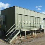
When constructing PLCs, the most important consideration is the system the PLC will control. This determines the type of PLC the system needed. Unitary PLCs are popular for small, low-cost systems. Modular PLCs commonly control small systems without cost limitations. Rack mounting PLCs are the preferred choice for larger systems. PLCs are commonly installed on or near the systems they control. PLCs must be easily accessible to workers for maintenance or replacement in the event of damage.
Repair and Maintenance
PLCs require regular maintenance and inspection. Before the installation of the PLC, the program must pass the FAT and may even need to undergo an SAT (site acceptance test). Once the installation is complete, the PLC is subject to regular inspection to ensure there is no damage. Verification of the input and output of the PLC ensures a smooth-running operation. In modular and rack mounting PLCs, each module can be removed and reinserted easily if they are damaged. A system shut off switch is recommended in the event a module requires replacement.