A pump is a mechanical device that utilizes energy to transport fluids. Various sources including electrical motors, wind power, or manual force application may provide the energy to make pumps operate. Industrial use of pumps ranges from coolant provision to fuel injection and transportation of petroleum products. In this article, you will learn about the different types of pumps, where those pumps are used, how they are selected, and maintenance and repair considerations.
Pump Types
The way energy is imparted to the target fluid determines the pump classification. Pumps can be divided into two broad classes: positive displacement pumps and dynamic pumps.
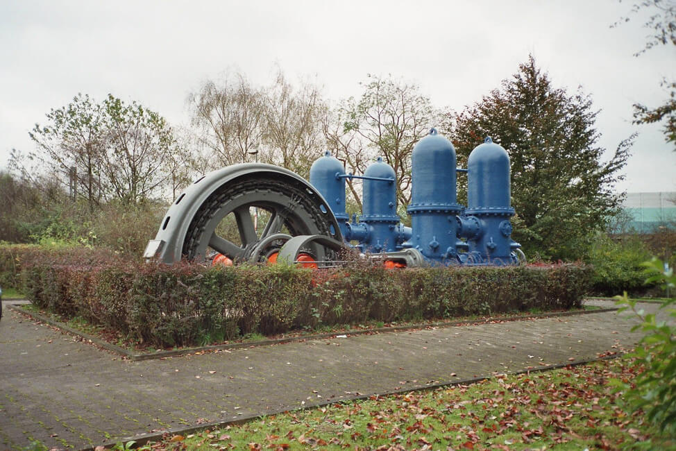
Positive Displacement Pumps
Positive displacement pumps move fluid by trapping a specified amount of fluid and then discharging the trapped fluid into a pipe. Usually, the cavity is larger at the inlet side and smaller at the discharge side. The fluid is forced to flow inside the pump as the cavity on the suction side expands. As the cavity shrinks the fluid flows out of it.
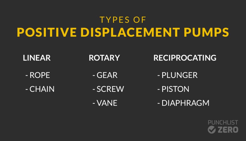
Positive displacement pumps use linear, rotating, or reciprocating means to push the liquid inside the closed cavity. The liquid stays inside the closed cavity until enough pressure is built to send it to the discharge system. The liquid velocity is not increased. This lower velocity of fluids becomes a desirable feature when the movement of viscous fluids or fluids with suspended solid particles is required.
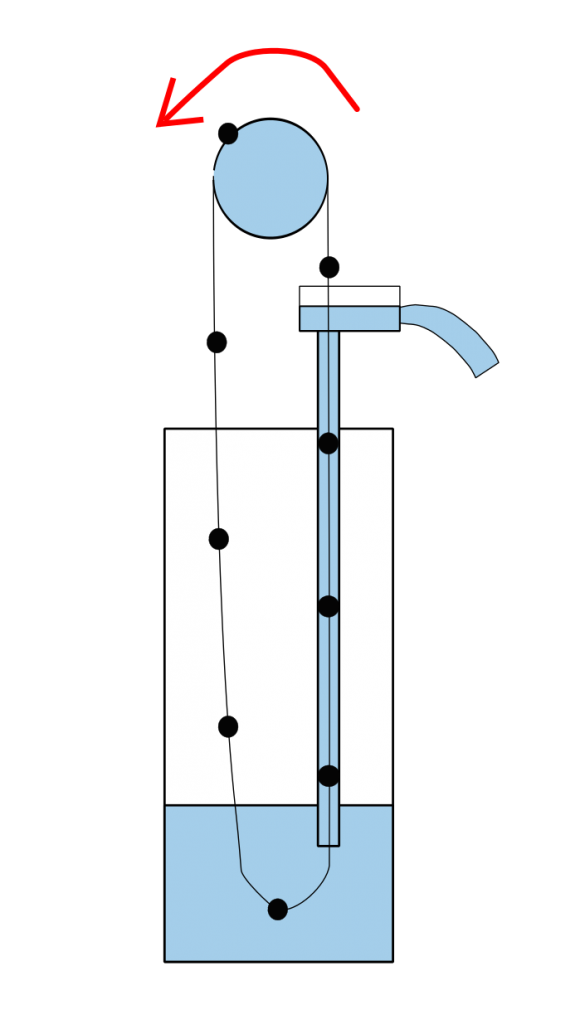
Linear Positive Displacement Pumps
A linear positive displacement pump is a looped rope or chain with affixed circular discs. The chain runs through a tube. The diameter of the tube is comparatively bigger than the diameter of the discs. The chain is dipped in fluid at one end. As the chain moves up the tube, water at the end is trapped in the discs and discharged at the top of the tube.
Linear positive displacement pumps are historically important, having been used as early as 700 B.C. However, their use today in commercial applications is limited.
Rotary Positive Displacement Pumps
Rotary positive displacement pumps include any parts that transport fluid from a reservoir to the discharge system via rotation. They are further classified into three types: gear pumps, screw pumps, and rotary vane pumps.
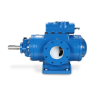
Gear Pumps
Two rotating gears move fluid in this type. As the gears rotate, the liquid is pushed between them and reaches the discharge system. Gear pumps are good fits for applications such as moving heavy fuel oils, paints, and sludge. Gear pumps are not as strongly affected by cavitation or irregular process flow as some of their alternatives. Cavitation is when bubbles are formed in the liquid from improperly applied design parameters, clogged filters or strainers, or pipe blockage.
Screw Pumps
Screw type rotors are mounted or cast on a shaft and build pressure as the shaft rotates. The fluid is pulled through the inlet and transports to the discharge. The clearance between the screws and the liner is very small so the fluid gains pressure as it moves through the cavity. Screw pumps can provide high flow rates no matter the viscosity of the fluid being pumped. Due to this characteristic, screw pumps are ideal for fuel transfer and lubrication applications.
Vane Pumps
A specific amount of fluid is sucked in and compressed to discharge via a rotating vane. Vanes are typically rectangular-shaped and mounted in slots on a rotor. As the rotor rotates, the vanes are forced to move inwards and outwards of the slots because of the asymmetrical shape of the casing. As the vanes move in and out of the slots, they trap the liquid inside them by touching the walls of the casing. The fluid moves in a circular motion and it is discharged at the discharge system. These pumps are known for their ease of maintenance and good suction characteristics. Rotary vane pumps are best suited for lower viscosity applications, such as solvents, fuel oils, and alcohol.
Reciprocating Positive Displacement Pumps
Reciprocating positive displacement pumps are characterized by an internal assembly that moves back and forth. This back and forth motion intakes and then discharges the fluid.
Reciprocating positive displacement pumps have three common configurations: plunger, piston, and diaphragm.
Plunger Pump
A rotary crank motion drives a plunger that pushes in and out of a chamber. Chamber pressure activates both the intake and exhaust port valves. Multiple cylinders are typically used, and the cylinder count is typically an odd amount, which helps prevent pulsation shocks.
Plunger pumps are used in higher pressure applications (1,000 psi to 30,000 psi). Plunger pumps are good fits for water and oil hydraulics, high-pressure cleaning applications, and metering systems.
Piston Pumps
In a single action piston pump, one inlet and one outlet valve open alternatively. At the time of suction, only the inlet valve is open while the valve at the outlet point remains shut. In the discharge sequence, the outlet valve opens and the inlet valve closes.
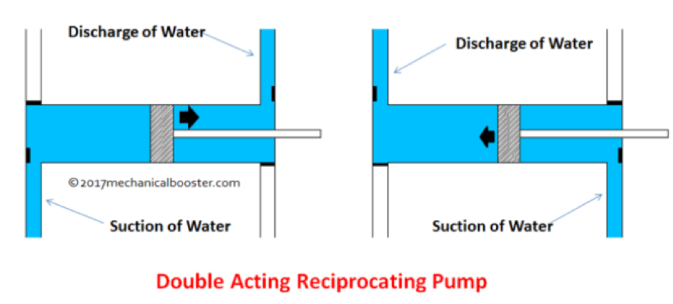
In double-action pumps, the suction and discharge take place simultaneously rather than in two separate motions. This bi-direction motion pulls fluid through two inlet ports and discharges fluid through two exhaust ports.
Diaphragm Pumps
Diaphragm pumps have a centrally located diaphragm (shown in black above). That diaphragm is flexed. The side to which it is flexed discharges the fluid downstream. The side away from the flexing action allows for fluid to be taken into the chamber.
Diaphragm pumps are frequently seen in “dosing” applications where a small amount of fluid needs to be added to a process stream. These pumps can handle corrosive, abrasive, and viscous liquids. Small mechanically activated diaphragm pumps can even be used as air compressors.
Dynamic Pumps
Dynamic pumps are also known as kinetic pumps. These pumps induce pressure and velocity to the target fluid. As it moves through the pump impeller some of the velocity is converted to the pressure to support the fluid movement towards the discharge. The main type of dynamic pump is centrifugal, but other niche applications of dynamic principles exist.
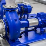
Centrifugal Pumps
A centrifugal pump rotates and dynamically imparts velocity and pressure to the fluid. The two main parts of the centrifugal pump which are responsible for energy changes inside the pump are the impeller and casing. The casing is responsible for collecting the discharged liquid via the impeller and converting some of the velocity to additional pressure.
Specialty Pumps
There are three speciality pump designs that utilize dynamic principles to generate pumping force.
Cantilever Pumps
Cantilever pumps have a long cantilever design without a bearing installed at the lower part of the pump. These are frequently used in sump pump applications and are a good fit for pumping slurries.
Jet Pumps
Jet pumps are typically inserted vertically direct into the process media. Multiple inlets draw in a constant stream of fluid and use pressure to create lift through suction. Jet pumps are a good fit for applications where the material that is pumped creates force needed to move through the pump. Jet pumps are frequently seen in downhole well applications.
Turbine Pumps
Turbine pumps consist of a rotary mechanism that is typically driven by an engine or an electric motor. They make use of pressure to move the fluid. In addition to the rotary part, turbine pumps consist of several impellers and vanes that discharge the fluid. Turbine pumps are used as alternatives to where the use of a submersible pump is impossible. They can be used in wells, tank applications, or in boosting applications.
Pump Controls
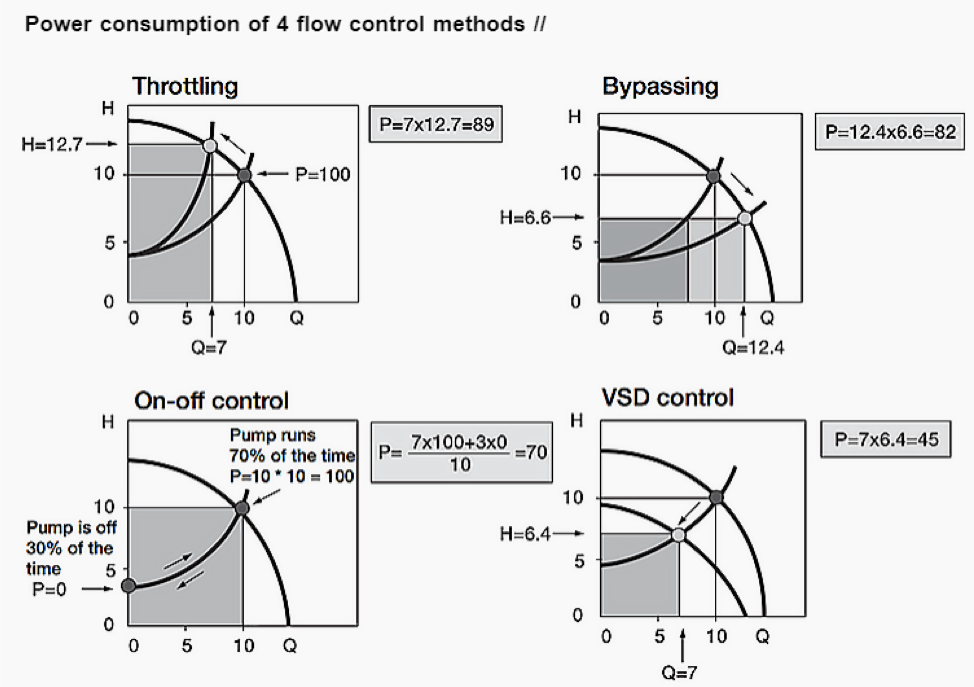
Pumping systems require variation in flow rates most of the time depending on discharge point and system needs. There are several control methods to meet these requirements. The most commonly used flow control techniques are: throttling, bypass, on-off control, and variable speed drive (VSD) control.
Throttling is when the pump inlet is manually adjusted to reduce flow. The losses are increased in the system by closing the valves which reduce the flow from constant speed pump. Throttling is a reliable way to ensure consistent flow, but wastes energy, increases valve wear, and is often noisy.
Bypass controls pumps water back to the pump inlet/suction to reduce the output flow. Bypass control is easy to simple and low cost, but the extra amount of fluid needs to go somewhere. To store the fluid a buffer tank may be required and frequent cycling may be a concern is well.
On-off control means the pump is either working or shut off to maintain the required flow. Frequency cycling is a concern in this schema, which is especially a concern when frequent modulation is required.
In the VSD schema, the output flow is controlled by varying the speed of the impeller. This is an accurate and reliable, but requires additional costly equipment.
Utility power concerns also play a role in determining the proper pump control methodology. Power is given by the multiplying flow rate (Q) by the pump head (H). This relationship is expressed as:
P = Q X H
The flow rate and pump head’s correlation is the same no matter which schema is used. As shown below, power consumption is a function of how the pump system is manipulated to achieve the needed process output.
Process Media
The choice of pump is significantly affected by the type of fluid that is being transmitted. Key properties that need to be considered include: acidity, operating temperature, and viscosity.
The acidity of the pump can degrade or corrode the pump’s internal parts. If the targeted fluid has a low PH, appropriate material choices for the wetted pump material must be made.
The operating temperature must be carefully monitored to ensure the pump does not get too hot. Hot media increases the corrosion rate of liquids, can destroy wetted parts, and even cause a phase change in the media which leads to cavitation.
Viscous liquids will necessitate the choice of a rugged pump. Viscosity may also cause degradation in centrifugal pump performance. When pumping viscous liquids, pump suction side losses are an important factor to consider. The viscosity of the liquid at the lowest anticipated operating temperature must be evaluated as the viscosity is inversely proportional to the temperature.
Selecting a Pump
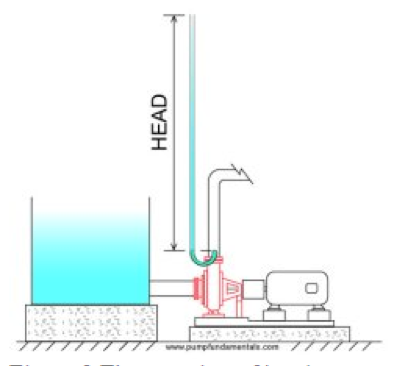
Knowing how to properly size a pump is a function of flow rate and net positive suction head. The flow rate depends on the required pump output which will likely be specified in process flow calculations. The required head is determined by calculating the static head minus friction head. The static head is the height measurement between the suction tank surface and the discharge pipe height. The friction head is a function of flow rate, pipe size, and pipe length. This head measurement is independent of type of fluid being pumped given that its viscosity is at least somewhat similar to water.
After determining the flow rate and the static head required, a pump curve can be read to determine if the pump is an appropriate fit for the application. The pump curve a graphical representation of the pump’s net positive suction head a pump and flow. A simplified version is shown below.
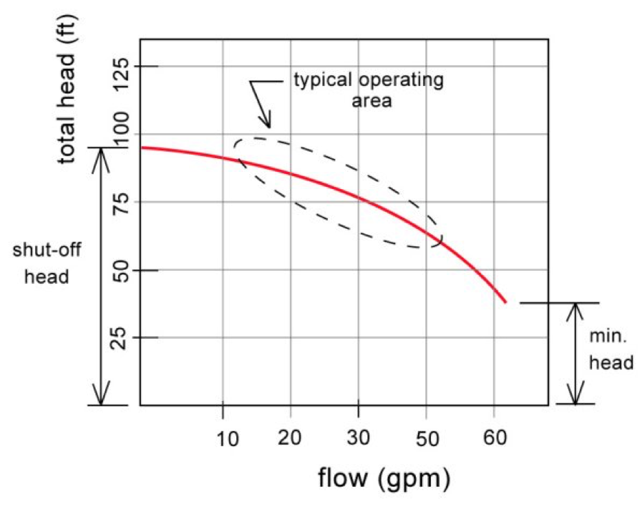
In reality, there are additional parameters that impact pump selection. These include horsepower and efficiency, and minimum flow. For centrifugal pumps, net positive head required (NPSHr) becomes is a significant concern. NPSHr is the minimum amount of pressure on the pump’s suction to overcome pump entrance losses. The pump will cavitate if NPSHr is not met. The consultation of an appropriate pump expert is crucial in making a final pump selection.
Maintenance and Repair Considerations
All pumps are prone to similar operating issues. The most major and frequently misunderstood operating problem is cavitation. Design parameters that result in cavitation may include a pump that is running too far right on the pump curve, poor piping design, or not meeting the NPSH requirements. Checking filters, strainers, and the inlet pipe on a regular basis will help avoid the clogs that create pressure imbalances.
Pump leakage and loss of pressure is another concern. The difference in pressure can lead to a backward motion of the fluid. Leakage is usually traced to a compromised o-ring or mechanical seal contamination.
Preventive maintenance protocols include checking for seal leaks and repair in a timely fashion, periodically checking the flow rate, pressure, and pump vibrations, as well as ensuring filter pressure drop is within required parameters.