Etukudo
Quiescent current is a very important parameter in battery-powered applications. This particularly holds true for products that are often on standby. In this article, you will learn the meaning of quiescent current, how to calculate it, its formula, and the difference between quiescent current vs other types of currents.
More About Quiescent Current
Quiescent current refers to the amount of current a circuit consumes when it is in a no-load, non-switching, but enabled condition. In other words, it is the current that a circuit draws when it is on standby or hibernation. This is a very important concept, particularly in battery-operated devices as most of these devices spend more time in standby mode than in operation mode.
As a result, the quiescent current is a major consideration in the design of such circuits. Thus, in these circuits, the quiescent current consumption of the constituent devices should be as low as possible to ensure long battery life. Generally, to achieve high AC performance metrics, the requirement is to have a value within the range of several hundreds of μA to a few mA.
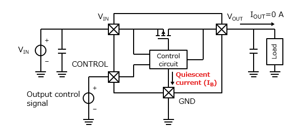
Furthermore, the quiescent current is an important characteristic of a low-dropout (LDO) linear voltage regulator. These types of regulators deliver output voltage that is close in value to the input voltage, thereby improving power efficiency. In this application, the LDO draws the quiescent current (IQ) to ensure proper operation of its internal circuitry. So, when the regulator is not actively supplying a load, this current flows to the ground (GND) terminal. This results in a slight difference between the input and output currents of the regulator as the formula below shows.
![\[ I_{Q}=I_{IN}-I_{OUT} \]](https://punchlistzero.com/wp-content/ql-cache/quicklatex.com-960e3d0a8013eef572d780a41c5fbd4f_l3.png "Rendered by QuickLaTeX.com")
How to Calculate Quiescent Current
Knowing the quiescent current value helps an electrical designer compare the low-power performance of different integrated circuits (IC). Generally, the value of the current depends on the overall system configuration, the IC’s internal design, and the external components around the IC. Because of its importance, designers use test circuits to obtain the quiescent current value of an ICs before deploying them. There are three main methods of doing so: self-test, two-amp loop, and three-amp loop.
Self-Test Circuit
The name of this method stems from its use of the device under test (DUT) to perform the test. The simple design and high reliability of this method make it a common choice. In addition, the self-test circuit reduces the test cycle duration and dependence on the external equipment. However, it can be slower, and parts with low quiescent current values are difficult to test using this method.
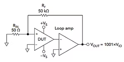
Two-Amp Loop
This method deploys another loop amplifier to perform the test. As a result, it is faster than the self-test method, and offers better control of DUT’s output voltage. On the other hand, this method is not suitable for DUTs with variable gain/phase. It also requires compensation to ensure the circuit’s stability.
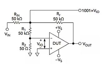
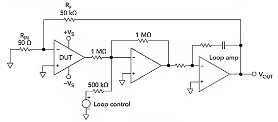
Three-Amp Loop
This method deploys two additional amplifiers to perform the test. Hence, it offers faster testing and very accurate control of the DUT output voltage. Also, in this method the DUT’s power supply can be greater than that of the loop amp. However, like the two-amp loop, this method does not suit DUTs with variable gain/phase, and there is a requirement for frequency compensation. In addition, there is a need to always have a 1 MΩ load on the DUT.
Quiescent Current Formula
The quiescent current value is often linked to the power dissipation from the circuit. Moreover, this loss in power (PLOSS) is a function of the input voltage (VIN), output volage (VOUT), output current (IOUT), and the quiescent current (IQ).
![\[ P_{LOSS}=\left ( V_{IN}-V_{OUT} \right )I_{OUT}+V_{IN}I_{Q} \]](https://punchlistzero.com/wp-content/ql-cache/quicklatex.com-d16d617cdbaccdcdebe123141d1a3f92_l3.png "Rendered by QuickLaTeX.com")
However, when the circuit is in an idle state – no-load condition – no current leaves the circuit and the quiescent current is as follows:
![\[ I_{Q}=\frac{P_{LOSS}}{V_{IN}} \]](https://punchlistzero.com/wp-content/ql-cache/quicklatex.com-704b8aa5d124810ed2039f985890ec04_l3.png "Rendered by QuickLaTeX.com")
Quiescent Current vs Other Current Types
Often, there are a lot of misconceptions concerning quiescent current and other current types such as leakage, supply, sleep, and shutdown. The following sections aim to clearly differentiate between these concepts.
Quiescent Current vs Leakage Current
Both quiescent current and leakage current flow when there is power input to a device. However, there are several differences between them which the table below highlights.
| Quiescent Current | Leakage Current |
| This current flow is desirable, as it keeps an IC active to enable a quick restart to an operational mode. | This is an unwanted flow of current due to insulation imperfections. This leads to an unintended conductive path. |
| Flows from only the input side of the circuit. Therefore, part of the overall input current. | Can flow from either the input or the output of the circuit. |
| Is prevalent in a no-load condition. | Occurs under normal operating conditions. |
| Quiescent current does useful work within the circuit. | Leakage current is regarded as an energy loss because it performs no useful work. |
| Generally, does not pose a risk to users or other devices. | If the circuit is not properly grounded, it can flow to the device chassis and pose a risk to operators. |
Quiescent Current vs Supply Current
Supply current refers to the total current a circuit draws from a power supply, irrespective of the loading condition. Moreover, quiescent current refers to only the part of the supply current the IC draws when the device is in a no-load, non-switching, but active mode. Thus, quiescent current is a subset of the supply current.
Quiescent Current vs Shutdown Current
It is easy, and often the case, to erroneously interchange the concepts of quiescent current and shutdown current, simply due to the similarities they share. First, the level of voltage in the system affects them both as their current values increase with input voltage. Also, both current values increase with increasing ambient temperature.
However, the quiescent and the shutdown current of a device are different. Basically, the quiescent current refers to the nominal current consumption when the IC is resting, but ready to work. Shutdown current applies when the device is asleep and not ready to work. Moreover, for quiescent current, the device is on with no load, but in the case of shutdown current, the device is switched off, but the battery remains connected to the system.
Quiescent Current vs Sleep Current
Sleep current is another concept that is easy to confuse with the quiescent current. The difference is that sleep current occurs when a device is put in a low-power state. Thus, there is a little load on the system, while quiescent current has no load. For example, when a computer is put on sleep mode, most subsystems are shutdown. However, the RAM is put into a minimum power state to store the machine’s memory and enable a response to a wake-up event.