Garcia
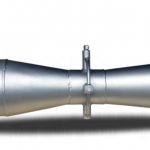
Restriction orifices (RO) provide economical and simple flow control in piping systems. This flow device limits the pressure or flow rate of a fluid to meet processing requirements. It consists of a mounted orifice plate between two flanges. This plate is composed of a circular metal disc with a specific hole diameter that reduces the fluid flow in the pipe.
In this article, you’ll learn about the types of restriction orifices, applications, optimizing performance, and sizing.
Types of Restriction Orifices
Restriction orifices do not have a singular design standard. Applicable references are ISO 5167-2, ISA RP 3.2, API -RP 550/551, API 2531, IEC 60534-8-3, API Manual of Petroleum Measurement – Chapter 4, AGA Report No.3, API MPMS 14.3.2, ISO 5024 and ISO 5168. Engineering specifications for a process system typically express requirements in terms of pressure drop, line sizing, and flow rate requirements. From this information, restriction orifice sizing may be obtained.
The three common types of restriction orifice are single-stage single hole, multi-hole single stage, and multi-stage.
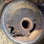
Single-Stage Single Hole

The single-stage restriction orifice provides the simplest flow impedance. It is usually a square-edged thin plate with a bore. The main intention of this plate with the orifice bore of the required size is for pressure loss. The use of a single-stage restriction orifice tends to maintain the standard pressure based on ISO 5167. The use of this plate puts the uncertainty of the flow pattern into consideration.
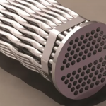
Multiple-Hole Single Stage Restriction Orifice
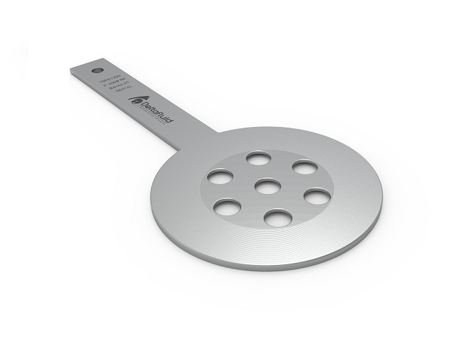
The second type of RO is the multiple-hole single-stage restriction orifice. It reduces noises and vibrations generated due to high velocity. This type of restriction orifice restraints the fluid from totally flowing through. The multiple holes distribute them to its distinctive streams to diminish the overall noise. Usually, when the high-velocity flow at the RO inlet is distributed through multiple holes, the tendency is it reduces the noise. Likewise, this type of RO is commonly used in order to avoid cavitation problems. This is evident when the flow distribution through several holes regularly improves the cavitation factor which in return reduces the overall noise.
Multi-stage Restriction Orifice Assembly
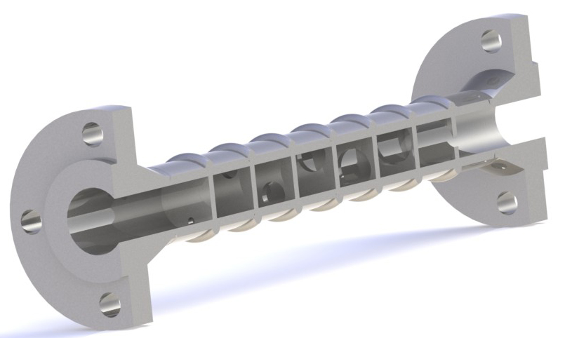
Lastly, the multistage restriction orifice assembly fits processes that require a higher pressure reduction ratio. This type of restriction orifice comprises several single-hole multi-stage devices, a few multi-hole multi-stage devices, and sometimes, a combination of the two. Multiple-stage restriction orifice assemblies arrange restriction orifices eccentrically. The minimum distance between each stage is usually the internal diameter of the pipe.
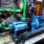
Applications
Engineers and others in charge of lessening the pressure or preventing the stream of materials need to be familiar with the taking after application of the restriction orifice:
- Pressure-controlling application. The restriction orifice plate is largely functional in steadfast flow condition with a fixed pressure drop requirement. A control valve may also require the installation of the RO when splitting pressure into two elements.
- Flow-controlling application. Moreover, the restriction orifice is sized up and installed based on the cavitation index. In this way, RO protects downstream components from erosion.
Optimizing Performance
- Avoiding sonic flow. Single-stage restriction orifice limits pressure drop to avoid choking or sonic flow. Sonic flow normally occurs when the required pressure drop is higher than the critical pressure drop. If this is neglected, sonic flow creates noise and vibrations in the pipeline and can cause mechanical failure.
- Avoiding cavitation. When there is subsequent cavitation and flashing especially in high vapor pressure liquid service, it is best to use restricted orifices. Cavitation happens when there is a massive pressure drop or when the pressure is below the vaporization pressure and thus, created vapor bubbles. Frequent cavitation may cause destructive breakdown of the pipe. At a minium, cavitation causes unwanted vibration and noise.
- Reducing noise. Using the wrong size RO may create a large amount of noise. Reduction of this noise via source control or path control are potential options. Between the two, source control provides the preferable and more effective method. When noise began to occur, it generates in the downstream pipes. High noise inside the piping system leads to vibration and subsequently may produce damage to the pipe. To reduce the RO noise, options exist such as altering the pressure drop. Pressure drop alteration changes the process media interaction and may move the system away from a natural resonance frequency. Increasing the number of reduction stages allows for a more gradual pressure drop and puts less stress on each stage. Optimizing multi-hole plate regulation of multi-hole plates, changes the pressure drop across each stage and expands the margin between the cavitation index and incipient cavitation index.
Sizing Restriction Orifices
Performance optimization factors into orifice sizing. Sizing factors include sonic flow, cavitation, and the minimum thickness.
Sonic Flow
Sonic flow occurs when a liquid is passing through a restriction point. There reaches a point when decreasing the downstream pressure does not increase the movement of mass through the restriction orifice. Calculating the expected sonic flow speed ensures this limit is not passed. This can be done by using upstream pressure(P1), downstream pressure(P2), and the Cp/Cv ratio(k).
![\[ \frac{P_2}{P_1} = (\frac{2}{K+1})^{\frac{k}{k-1}} \]](https://punchlistzero.com/wp-content/ql-cache/quicklatex.com-bf5adaba711343acc3795abf425d621b_l3.png "Rendered by QuickLaTeX.com")
Cavitation
This occurs when the pressure after the orifice drops below vaporization pressure causing bubbles to appear into the liquid. Variables used in this calculation include initial pressure(P1), the pressure at the narrowest point of the orifice(Pt), and the vapor pressure of the liquid(Pv). The cavitation index of the orifice should not surpass the cavitation index of the liquid.
![\[ Cavitation \; Index = \frac{P_1 - P_t}{P_1 - P_\nu} \]](https://punchlistzero.com/wp-content/ql-cache/quicklatex.com-d14253c4053063121f43e96ee78f6b68_l3.png "Rendered by QuickLaTeX.com")
Calculating Thickness
Minimum thickness for the restriction orifice requires calculation. The beta ratio(β), the maximum change in pressure(Pl) the pipe ID(D), and the yield strength of the material(σy)are involved in this calculation. The beta ratio is the ratio of the orifice diameter to the pipe inner diameter.
![\[ T_{Minimum} = (\frac{(0.681 - 0.651\beta)Pl}{27.73\sigma\gamma})^{0.5} D \]](https://punchlistzero.com/wp-content/ql-cache/quicklatex.com-965b4e2c4052034f8e1618fe842dcda1_l3.png "Rendered by QuickLaTeX.com")