Etukudo
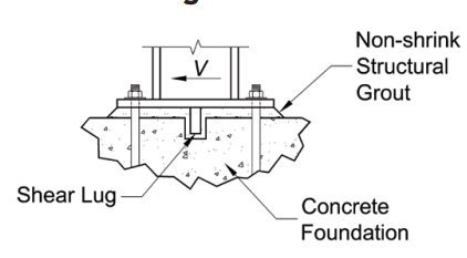
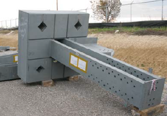
A shear lug refers to a steel embedment, which forms part of an anchorage that transfers lateral loads to a concrete foundation. Typically, a welder attaches it to the base plate of an anchor in applications involving significant shear loads.
In this article, you will learn the purpose of shear lugs, types, their design considerations, and the design calculations.
Purpose of Shear Lug
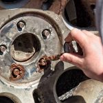
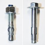
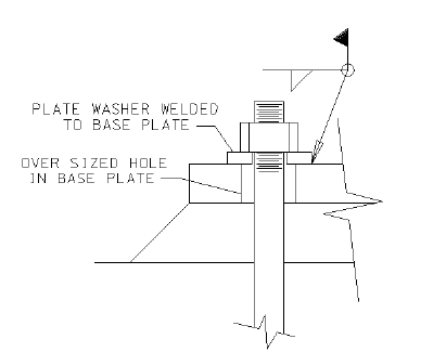
Anchoring a piece of equipment to a concrete floor or base, is common practice in the engineering industry. Moreover, the nature of the anchor depends on the predominant forces that will be acting on the structure. For small to moderate shear loads, anchor bolts provide sufficient resistance that caters for the full load. However, as the lateral loads increases, the use of shear lugs becomes imperative. Because the combination of shear and tensile forces adversely affect the capacity of anchor bolts. As a result, it is common to fabricate base plates with oversize holes, thus, exempting anchor bolts from bearing lateral loads.
Typically, they are used in anchorage in the following situations:
- The shear design strength of the anchors is less than the magnitude of lateral loads acting on them.
- Also, where the number of anchors needed for shear transfer is impractical.
- Finally, when there is need for alternative means of shear transfer into the concrete.
Types of Shear Lugs
Generally, the classification of shear lugs depends on the method of installation and its configuration.
Classification by Installation Method
Their attachment to concrete is basically done in two ways.
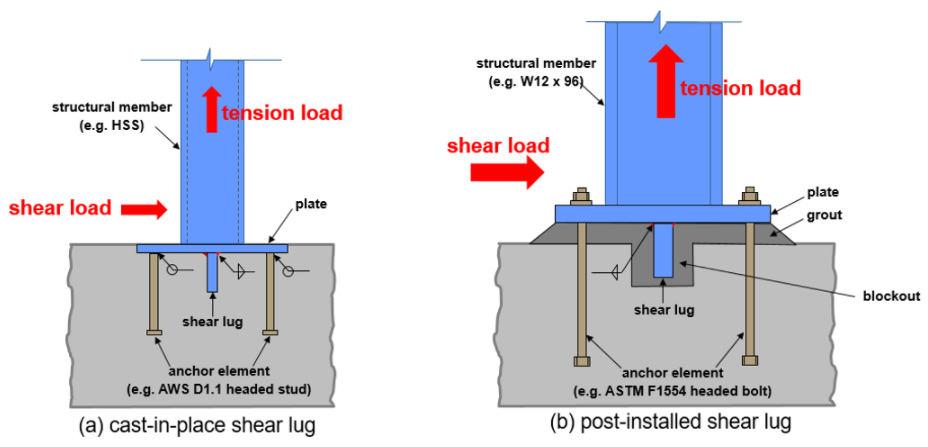
- Cast-in-place: This method of installation requires the shear lug to be cast in wet concrete before the concrete sets. Ideally, this approach is suitable when there is need for large embedment lengths due to significant shear loads.
- Post-installed: For this method, a blockout set in the concrete receives the shear lug and is then filled with grout.
Classification by Plate Configuration
Typically, shear lugs consist of one or more pieces of plate. Moreover, the direction and magnitude of the design shear force determines the configuration of the plates.
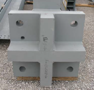
- Crossed Plates: This is the ideal configuration for resisting lateral loads in two orthogonal directions.
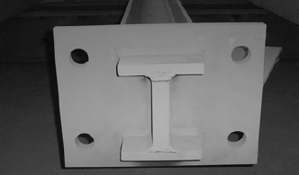
- H-shape Plate: As the demand for loading capacity and lug embedment increases, configurations such as the h-shape offer more suitable options.
- Large Box Shape: When the shear capacity of the anchor is to be greater than that of the structure it supports, it is common to find the shear lug much larger in size and box shaped. In addition, this is a configuration that suits structures that will be subject to seismic loads.
Shear Lug Design Considerations
The resistance to lateral forces on a structure comes from the combination of the shear lug and concrete foundation. Thus, it is necessary to evaluate the possible failure modes of these two entities.
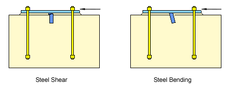
Steel Failure
This failure mode has to do with the shear lug material. Moreover, to avoid this mode of failure, it is critical to evaluate the material’s shear and bending capacities with respect to its properties and physical dimensions of the lug. If the steel capacity is insufficient, it could fail through shear or bending.
Weld Strength
The weld joint between the lug and the underside of the anchor base plate provides a point of possible failure. Thus, it is necessary to access the shear and bending reactions there and compare them to joint resistance.
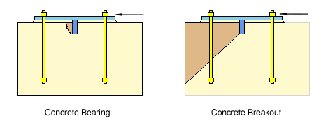
Concrete Bearing
As the lug embedment in concrete increases, so does the concrete’s ability to bear the increase in lateral pressure. However, design guidelines limit the bearing depth to two times the lug’s thickness. In any case, the lateral pressure should be less than the concrete bearing strength.
Concrete Breakout
The effective stress area is the basis for determining the design strength of the concrete against breakout. In both plan and elevation, a 35° plane from the bearing edges from the shear lug to the free surface is what defines this effective stress area.
Shear Lug Design Calculations
After obtaining the design loads on an anchor, engineers must verify the capacity of the concrete foundation and shear lug to resist these loads. This section reviews a few of the verification calculations.
Bearing Verification of the Shear Lug in Concrete
Calculations should verify that the effective shear force on the anchorage (τeff), is less than or equal to the lug’s design bearing resistance in concrete (VRd,c). Moreover, the design bearing resistance of the shear lug in concrete is a product of its effective length (Leff,n), the flange width (bn), and the concrete design strength (fcd).
![\[ V_{Rd,c} = b_{n}\times L_{eff}\times f_{cd} \]](https://punchlistzero.com/wp-content/ql-cache/quicklatex.com-7cf5ebe127f70e7febbc869ece612b9c_l3.png "Rendered by QuickLaTeX.com")
![\[ \tau _{eff}\leq V_{Rd,c} \]](https://punchlistzero.com/wp-content/ql-cache/quicklatex.com-ec0560ce8a8110c9b6782466eff99553_l3.png "Rendered by QuickLaTeX.com")
Satisfying this design criterion prevents concrete bearing failure.
Shear Verification
For the lug, its design shear resistance (VRd) should be equal to or above the effective shear force on the anchorage (τeff). This design resistance is a function of the shear area of the lug (Aτ), its material yield strength (fy), and the material partial factor (γM0).
![\[ V_{Rd} = A_{\tau }\times \frac{f_{y}}{\gamma _{M0}\sqrt{3}} \]](https://punchlistzero.com/wp-content/ql-cache/quicklatex.com-47a398e9c8f2ea6534db44d0c12cdaee_l3.png "Rendered by QuickLaTeX.com")
![\[ \tau _{eff}\leq V_{Rd} \]](https://punchlistzero.com/wp-content/ql-cache/quicklatex.com-914391ed1bda3d3d3c0bac5172b1a3f3_l3.png "Rendered by QuickLaTeX.com")
The design criteria above are just snippets of the entire design process. Further details and guidance pertaining to this process are elaborated in standards such as ACI318-19.