Etukudo
A vortex refers to the rotation of a fluid’s core while draining from a vessel. Moreover, engineers use vortex breakers to prevent the formation of vortices due to their effect on flow. In this article, you will learn about vortex formation, its effects on flow, vortex breaker design, and applications in the industry.
Vortex Formation
To understand the formation of vortices, it is important to review the concept of the Coriolis effect. The Coriolis force is an inertial force, which acts on objects in a frame of reference that rotates with respect to an inertial frame. Furthermore, for a draining fluid, this force acts at right angles to the direction of flow, and never points towards the outlet nozzle. As a result, the fluid is drawn away from the outlet, leading to a swirling effect on the flow. A graphical representation of this is in the figure below, with the direction of the Coriolis force in red, the initial flow of the fluid in blue, and the resultant flow in green.
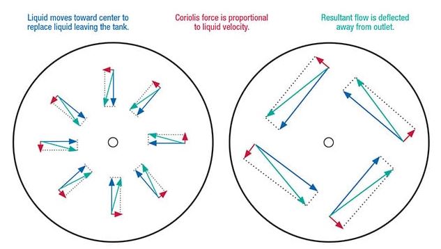
Hence, in a tank without a vortex breaker, the formation of vortices quickly grows until it obstructs flow from the outlet. In addition, it is important to note that Coriolis force is directly proportional to the velocity of the flow. Thus, an increase in flow velocity leads to more vortices, which are detrimental to flow.
Evaluating Vortex Formation
Before undergoing vortex breaker design, it is necessary to check if a flow is susceptible to the formation of vortices. Accordingly, engineers assess flows for the presence of vortices via laboratory experiments on prototypes or by undertaking Large Eddy Simulations on Computational Fluid Dynamics. However, these sophisticated approaches require a significant investment of time and other resources.
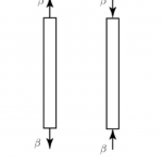
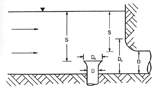
In contrast, a simplified approach exists, which involves checking the value of the submergence of the flow outlet. This minimum submergence (S) denotes how to avoid vortex formation in a tank. S depends on the outlet diameter (D), and the Froude number of the flow (Fr).
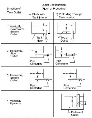
For flush or protruding outlet configurations, the minimum convergence to avoid vortex formation is given as:
[Latexcode]
![\[ S=D\left ( 1+2.3Fr \right ) \]](https://punchlistzero.com/wp-content/ql-cache/quicklatex.com-83675440bf2eea5e5c0139892ed2c241_l3.png "Rendered by QuickLaTeX.com")
This applies under certain conditions which include:
- Uniform approach flow across the channel width.
- Flowrate below 2 ft/s.
- Elimination of flow separation, abrupt changes in flow direction, and stagnant flow areas.
The minimum allowable submergence can be calculated using the diameter of the bellmouth intake.
![\[ S=1.5D_{O} \]](https://punchlistzero.com/wp-content/ql-cache/quicklatex.com-bf3c3ff913291dafbbb097e75d1540ba_l3.png "Rendered by QuickLaTeX.com")
In any case, engineers can still estimate the minimum allowable submergence for a bellmouth intake as a function of Froude’s number and the outlet diameter.
![\[ S=D\left ( 1+Fr \right ) \]](https://punchlistzero.com/wp-content/ql-cache/quicklatex.com-d3a92025b8640cacaf81ed2c5f9497c4_l3.png "Rendered by QuickLaTeX.com")
Froude number is a dimensionless flow characteristic that is a function of the flow velocity (v), acceleration due to gravity (g), and flow diameter (D).
![\[ Fr=\frac{v}{\sqrt{gD}} \]](https://punchlistzero.com/wp-content/ql-cache/quicklatex.com-efe9618b775db2bc581c831b97308c08_l3.png "Rendered by QuickLaTeX.com")
Effect of Vortices on Flow
Other than obstruction of flow, the formation of a vortex has several detrimental effects during fluid drainage.
Gas Entrainment
In a two-phase flow (gas and liquid), engineers often achieve separation using gravity. Moreover, this involves draining the liquid from the bottom of the tank and pumping it to a destination of use. However, the presence of vortices in such an application draws gas down the drain. Therefore, cavitation may occur in the discharge pump and hamper the performance of the downstream processes.
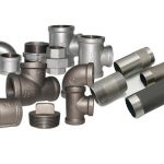
Erosion of Pipe and Fittings
Erosion and corrosion of flow channels are more difficult to prevent in multi-phase flow. Because vortices disrupt flow patterns and make separation of the phases challenging at drains, it makes the nozzle and piping downstream of the drain susceptible to erosion and corrosion.
Pressure Drop
The presence of a vortex cone leads to a reduction of the flow pressure. Moreover, studies show that the longer the cone, the greater the pressure drop. Consequently, there will be an increase in pumping requirements downstream of the drain.
Vortex Breaker Design
A typical vortex breaker design targets the prevention of flow swirling through the aid of baffles. According to the Pressure Vessel Handbook by Eugene Megyesy, the key parameter in designing a vortex breaker is the diameter of the outlet pipe (D). Moreover, recommendations from this handbook, which provide guidance to engineers in vortex breaker design include:
- The baffle diameter should be at least twice the diameter of the outlet pipe (2D). However, in applications with severe swirling conditions, the baffle diameter can be as much as four times the outlet pipe diameter (4D).
- For a grating baffle, its diameter should be a maximum of one-third of the vessel diameter or four times the outlet pipe diameter (4D). In addition, its clearance from the outlet pipe should be half of the pipe diameter (0.5D).
- In the case of disc and cross-type baffles, the clearance should be equivalent to the outlet pipe diameter (D). But could be several inches if other requirements demand a larger clearance.
Types of Vortex Breakers
There are different types of vortex breakers that align with the needs of diverse applications. The most popular ones are the disc type and the cross-type.
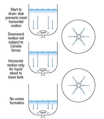
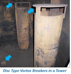
Disc Type
This type has baffle plate is set up to impede axial flow without obstructing radial flow. As a result, the baffles constrain liquid at the bottom of a tank to move horizontally towards the exit nozzle, while the liquid above moves downwards to replace it. Consequently, limiting the Coriolis force to only the flow region within the clearance zone. These are the most common type of vortex breakers as engineers see them as very effective.
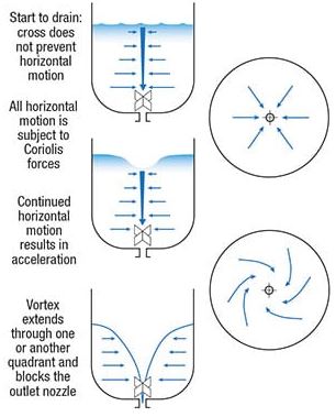
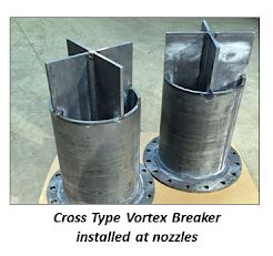
Cross Type
The design of this type is to eliminate the formation of vortices by providing a barrier to rotational flow. Nevertheless, small cross-type baffles do not have a significant effect in preventing vortex formation. Thus, the larger they are, the more effective. As a result, most designers prefer to use the disc type.
Application of Vortex Breakers
Vortex breakers are popular in a variety of applications to maximize drainage flow rates, minimize pressure losses across drains, ensure proper separation of flow phases, and reduce erosion in pipe fittings.
Clean-in-place Applications
In the food and pharmaceutical industries, there are strict requirements on flow rates for cleaning tanks. As a result, flow should exceed a threshold speed to achieve the set levels of cleanliness. But, the presence of vortices causes liquid holdup, which allows dirt to accumulate in the tank. Thus, the use of vortex breakers prevents this.
Drainage Applications
Having liquid holdup in bathtubs, sinks, and other drainage tanks is undesirable. Therefore, vortex breakers, especially of disc type, are common in these systems to improve flow rates.
Flow Separators
The presence of vortices leads to gas entrainment in drains, thereby lowering the efficiency of separators in multi-phase flow. Using vortex breakers ensures that those flow patterns that lead to gas entrainment are not present.
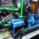
Hydropower Facilities
Several studies show that swirling flow leads to a reduction in the effectiveness of an intake in turbine systems. In addition, a vortex can alter the angle of attack on impeller blades, which reduces pump efficiency. As a result, engineers deploy guide vanes upstream of turbines and pumps in hydropower facilities to ensure that vortices are not present.