Etukudo
What is pump head? Understanding this question provides a fundamental understanding of force flow systems. It refers to the height that a pump can raise fluid up to and its measurement is usually in feet or meters. In this article, we will learn more about pump head, review its formula, and the relationship between head and flow.
More about Pump Head
Generally, pump head is one of the parameters of interest when dealing with forced flow systems. Specifically, it measures the maximum height that a pump can take a fluid against gravity and provides a way to rank pump capacity. There is a misconception that head and pressure are the same due to their directly proportional relationship.
However, head and pressure are inherently different. The head is a measure of energy, while pressure quantifies the force required to drive the liquid. Because the liquid’s density determines the force requirement, pressure depends on the liquid type, but the head does not. As a result, head provides a preferable standard for rating pumps.
Factors Affecting Pump Head
Although the pump head is independent of the type of fluid, there are factors that influence its value.
- Pump Power: This is the most important factor in determining what pump head is achievable. The higher the power, the greater the head. But, the size of the pump influences the wattage output, due to technical issues such as heat dissipation. So, the size limits the power output, and consequently, the head.
- Pump Motor Speed: An increase in the motor speed results in an increase in the head under a certain wattage level. For AC pumps, their speed is a function of frequency, so it is constant. On the other hand, it is easier to increase the motor speed in DC pumps, which enables them to attain a higher head.
- Inner Diameter of the Pump Outlet: Because pressure is force per unit area, a smaller area enables the delivery of greater force. Designing the structure of a pump with a small inner diameter at the outlet increases the pressure and head values.
Formula
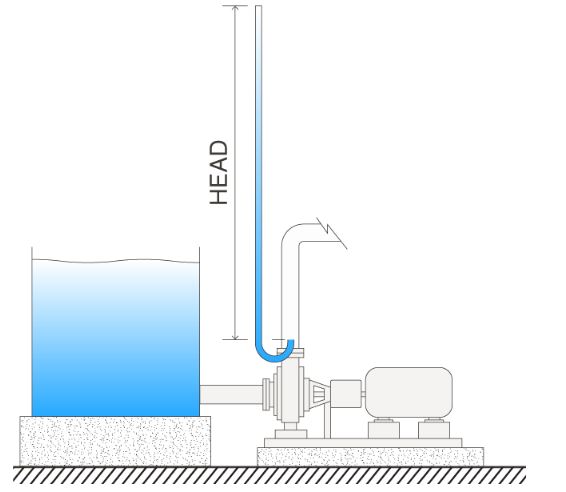
To adequately represent the head mathematically, it is necessary to distinguish between the various types. What is known as the pump head is just a fraction of the total head in the system and is also referred to as a static delivery head. The other fraction of the total head is the static suction component, which is the maximum depth from the pump to the water level in the suction tank or well. So, the total value in any system is an aggregate of its suction and delivery/pump components as follows:
![\[ Total Head = Pump Head - Suction Head \]](https://punchlistzero.com/wp-content/ql-cache/quicklatex.com-65ffecd82731f694341675bea5c9e514_l3.png "Rendered by QuickLaTeX.com")
The negative sign before the suction head in the equation is because its measurement is downwards, opposite in direction to the delivery head. If the suction tank or well water level is above the pump, then the suction head is negative. Thus, adding to the total head. But, if the water level is below, it is positive, resulting in a reduction of the total head.
Specifically, for the pump head (H), it can be expressed as a function of the pump output power (PQ), density of the fluid (ρ), flowrate (Q), and gravitational constant (g).
![\[ H=\frac{P_{Q}}{\rho gQ} \]](https://punchlistzero.com/wp-content/ql-cache/quicklatex.com-c13fc8d7448be9a6ab1abf7e42d59593_l3.png "Rendered by QuickLaTeX.com")
Bernoulli’s equation offers another way of calculating the pump head in a system as a function of several parameters. These include: the pressure at the suction and discharge of the pump (ps and pd); the fluid velocity at the suction and discharge (vs and vd); as well as the geodetic heights at suction and discharge (zs and zd).
![\[ H=\frac{p_{d}-p_{s}}{\rho g}+\frac{v_{d}^{2}-v_{s}^{2}}{2g}+z_{d}-z_{s} \]](https://punchlistzero.com/wp-content/ql-cache/quicklatex.com-48889ce61ee0675debbc62f5901ff275_l3.png "Rendered by QuickLaTeX.com")
Head vs Flow
The relationship between the head value, and the resultant flow rate is unique for each pump. Mostly, it is the basis of pump selection because it indicates the individual pump’s operating field. Therefore, it shows its suitability for the desired application. It is common to refer to a plot of this head-flowrate relationship as the performance curve. Generally, this curve follows a similar pattern for all pumps as the example below shows.
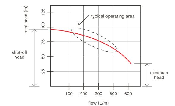
Another important consideration regarding pump performance is losses in the system. Overall, they are classified into major losses and minor losses. Major losses, as the name implies, have a greater impact and are due to friction between the operating fluid and pipe internal wall. Thus, longer distances of flow and rougher pipe surfaces lead to more frictional losses. Minor losses result from features along the flow path such as changes in flow cross-section, direction, and the presence of appurtenances. Each feature possesses a standard coefficient that serves in evaluating the amount of loss in the system. As a result of these losses, the pump would perform sub-optimally with pump head and flowrate values less than recordings on its performance curve.