Fracture toughness is a physical property of matter. It describes the resistance of the material to fracture while it has cracks. It is different than simple toughness which is defined as the capacity of any material without cracks to absorb energy without breaking up. In this article, you’ll learn the fundamentals of fracture toughness and its importance to material selection, its calculation process, and testing and modification considerations.
Property Characteristics
The fracture toughness of a material KI may be defined as the stress intensity factor for crack growth under certain given conditions. Such crack growth will result in immediate disintegration of the material.
Fracture toughness indicates the amount of stress required to propagate a preexisting flaw. It is a highly important material property as the occurrence of flaws is not completely avoidable in the fabrication process. Flaws appear as cracks, voids, weld defects, or any combination of these. Since one can never be sure if a material is flawless, it is a usual practice to assume that a flaw of some size will be present in some of the components. Therefore one uses the linear elastic fracture mechanics methods to design critical components. This approach takes into account the flaw size, geometry, loading conditions, and fracture toughness to estimate the capability of the component to resist major fatal fractures despite material flaws.
Toughness measures the required energy to resist the fracture. This property may possess more importance than the tensile properties, depending on the conditions where that component is used. The term impact strength is often used to measure the toughness of the material. However, this is not correct as it should be impact energy. Toughness strongly depends on the rate of loading, temperature, and the presence of stress concentrations.
Fracture Modes
The fracture process consists of two stages; crack initiation and crack propagation. The propagation of a crack that results in a fracture provides information about the mode of that fracture.
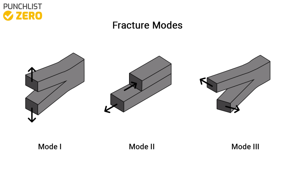
There are three fracture modes.
- Mode I: Also called Opening Mode, tensile stress applies perpendicularly to the crack plane.
- Mode II: Also called Sliding Mode, in-plane shear stress acts normally to the crack.
- Mode III: Also called the Tearing Mode, shear stress applies parallel to the crack and the crack front.
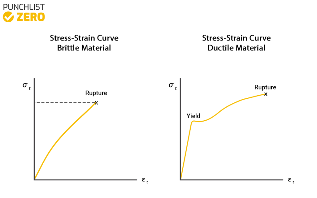
Fractures categorize as either ductile or brittle depending on the plasticity of the material. We can also say that the character of the fracture changes is based on the amount of plastic deformation that a material can tolerate. If some significant plastic deformation takes place during or before the propagation of the crack, then the fracture categorizes as a ductile fracture. Otherwise, if the only deformation takes place at a micro level then the fracture would be called a brittle fracture. Plastic deformation is a sign of an impending fracture. However exactly defining the difference between brittle and ductile fractures is difficult. This is because several factors come into play that affect the material deformation. This includes the rate of stress, rate of loading, the ambient temperature, and the crystal structure of the material.
Material Considerations
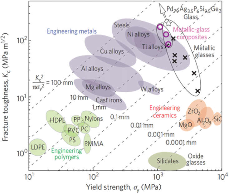
Fracture toughness ranges massively over different materials. Metals and alloys have the highest values as they are highly resistant to cracks. Ceramics have a lower fracture toughness despite possessing high strength. Polymers generally have low fracture toughness, but engineering composites of ceramics and polymers produce higher fracture toughness values. Wood, glass, cement, concrete, etc. have lower values. Foams and polymers possess some of the lowest fracture toughness.
Fracture Toughness Calculation
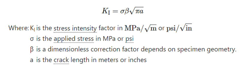
The stress intensity factor amplifies the magnitude of the applied stress to predict failure. The stress intensity factor is a function of loading, crack size, and structural geometry. The stress intensity factor represents as the following equation:
A common culprit that leads to a high stress intensity factor is fatigue.
Fatigue Considerations
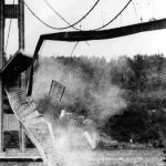
Fatigue cracking is one of the primary damage mechanisms of structural components. Cyclic stresses in a material are the cause of fatigue cracking. The name “fatigue” means that the material becomes “tired” of the stresses and it fails at that point. Fatigue damage is quite dangerous because even though the original bulk design strengths are not exceeded the minute cracks appear, which are a warning sign but are difficult to detect.
The fatigue life is an important parameter that can be defined as the number of loading cycles required to initiate a fatigue crack and which can propagate to a critical size. Fatigue failure occurs in three stages:
- 1 – Crack Initiation
- 2 – Crack Growth
- 3 – Rapid Fracture
Slip bands are the result of cyclic loading and dislocations which play a big role in the fatigue crack initiation. In this first stage, dislocations accumulate near the surface and form structures called persistent slip bands. They serve as stress risers and that’s where tiny cracks start to appear. These small microcracks form along planes of high shear stress areas which is about 45o to the loading direction.
In the second stage, some microcracks join together and begin to propagate through the material, perpendicular to the tensile stress. Eventually, the smaller cracks convert to larger cracks and with further cyclic loading, the growth of the dominant crack grows until the component can no longer support and a fracture occurs. Once the fracture toughness is exceeded, rapid fracture forms, and fatigue failure occurs as the third stage of this phenomenon.
Testing and Modification Considerations
The use of fracture mechanics is quite important in determining the maximum flaw size that a material can withstand before completely failing. Cracking on a thick plate is worse than on a thin plate because of plane strain conditions. At the tip of the crack, the plastic zone is quite small, with a high-stress gradient across the plastic zone. There are high triaxial stresses present at the tip of the crack. As the material thickness increases, the appearance of fracture changes due to a large number of triaxial stresses.
In thin plates, the fracture occurs in both the ductile and brittle modes. Under plane strain conditions, when the plate is thick enough the fracture is flat, and the fracture stress is constant with increasing thickness. Different combinations of test samples determine the plane-strain fracture toughness.
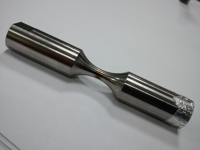
A test technician machines a notch in the test specimen and makes it sharper by fatiguing at low cycle and high strain until the crack is about the width of the test specimen. This crack length is measured by including the length of the crack and the notch. Testing of the sample is performed by applying the tension of the test sample. Tension increases and recording of the crack displacement occurs until failure.
Modification of a material’s fracture toughness occurs via reducing the impurity content and grain size. This typically involves a heat-treating process. Composite material fracture toughness may be increased via toughening resins and manually altering grain boundaries.