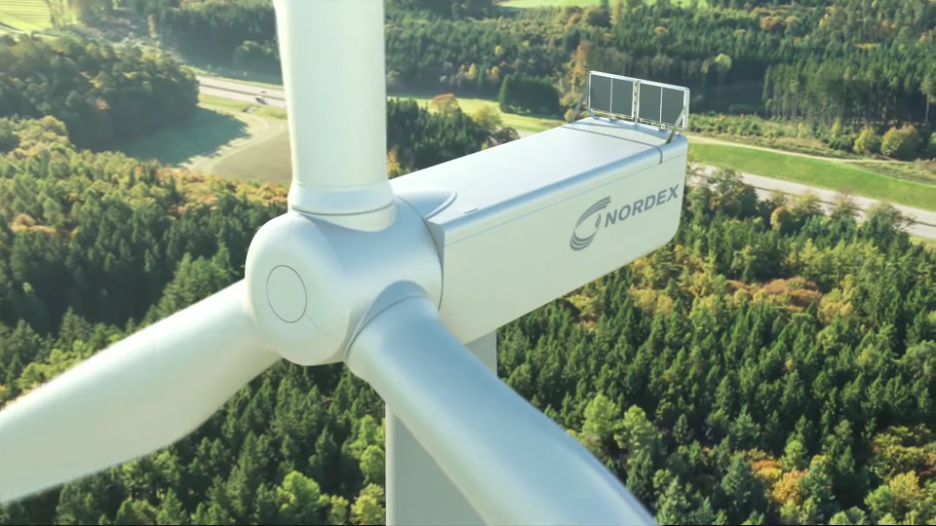
Courtesy: NORDEX
The efficiency of wind turbines is significantly influenced by the design of their blades. Finding the best wind turbine blade is a primary focus for engineers and researchers in the field of renewable energy. Advancements in technology and material science have led to significant improvements in blade design over the years. This article delves into the aspects of the best blade design for wind turbines, explores common materials used in blade construction, and discusses the typical lifespan of these critical components.
Best Blade Design for Wind Turbine
The “best” blade design for wind turbines is determined by several key factors: aerodynamic efficiency, cost-effectiveness, durability, and minimal environmental impact. Optimal designs ensure that wind turbines convert the maximum amount of wind energy into electrical power.
Factors Influencing Blade Design
Aerodynamic Efficiency
The shape and size of the blades are paramount in determining a turbine’s aerodynamic efficiency. The aerodynamics of wind turbine blades encompasses the study of airflow and its interaction with the blade surface. A well-designed blade minimizes resistance while maximizing lift, thereby extracting maximum energy from the wind. The design process involves sophisticated modeling techniques to simulate wind flow and predict performance under various conditions. This design principle enables the blades to rotate the turbine’s rotor more effectively, even in low wind speed conditions.
Environmental Considerations
Blades must withstand the specific environmental conditions, including variations in wind speed, density, and direction. This adaptability ensures consistent performance, power generation, and longevity.
Material Durability
The choice of materials directly affects the blade’s durability and performance. Optimal blade designs also consider material flexibility and durability to withstand the physical stresses exerted by wind forces. The ability of a blade to bend slightly without breaking reduces the risk of damage during high winds, thereby extending the turbine’s operational life. Innovations in material science continue to enhance the strength, flexibility, and lifespan of turbine blades, driving advancements in wind energy technology, including:
- Use of Carbon Fiber Composites: One significant innovation in the field of wind turbine blade materials is the increasing use of carbon fiber composites. Unlike traditional materials like fiberglass, carbon fiber offers a superior strength-to-weight ratio, which allows for the construction of longer, more efficient blades. This material innovation enhances the aerodynamic performance of wind turbines and contributes to their overall durability and lifespan. For instance, the introduction of carbon fiber has enabled the production of blades that can exceed 100 meters in length, significantly increasing the energy output of wind turbines.
- Bio-based Epoxy Resins: Another cutting-edge development is the use of bio-based epoxy resins in the manufacturing of turbine blades. Traditional epoxy resins, derived from petrochemicals, provide a matrix in composite materials but pose environmental and health concerns. In contrast, bio-based epoxies, made from natural sources such as plant oils, offer a more sustainable and less toxic alternative. These materials reduce the carbon footprint associated with blade production while maintaining the mechanical properties required for high-performance turbine blades.
Design Features
The most efficient blade designs incorporate specific features tailored to aerodynamic efficiency, cost-effectiveness, durability, while minimizing environmental impact.. The shape of the blade, often inspired by airfoil profiles, minimizes drag and maximizes lift, enhancing the turbine’s ability to capture wind energy. The length and pitch (angle) of the blades optimize specific wind conditions and operational requirements.
Design Types
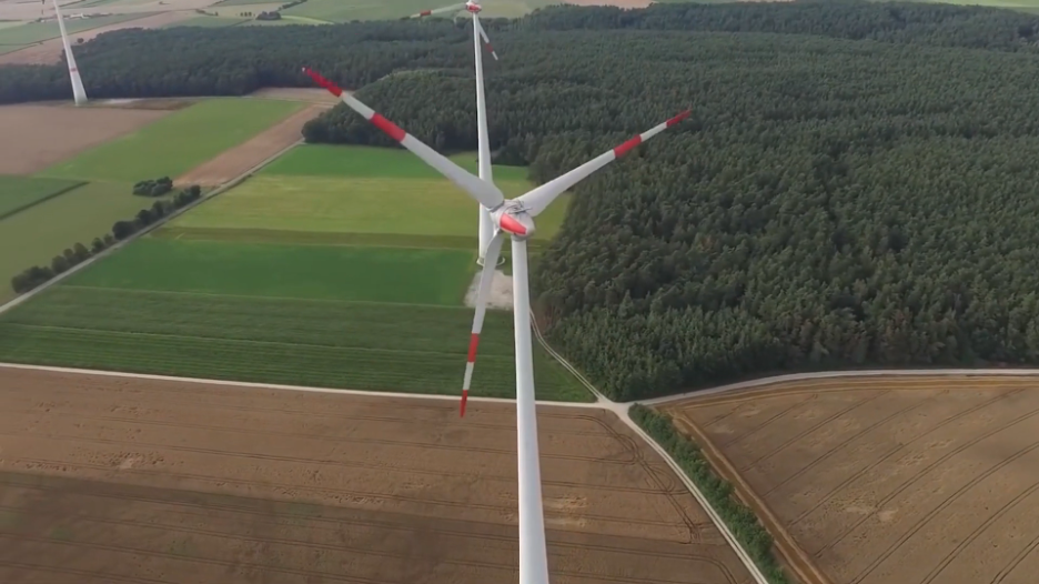
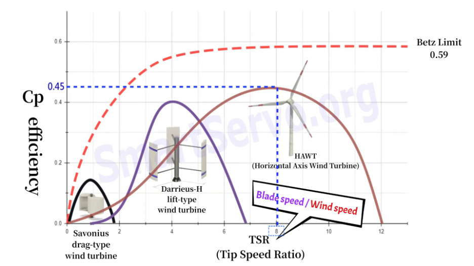
The horizontal-axis wind turbines (HAWTs) are the most common, characterized by their upward-standing, propeller-like design. This configuration provides superior efficiency in converting wind energy at high wind speeds.
Vertical-axis wind turbines (VAWTs), while less common, offer advantages in lower wind conditions and are more versatile in urban or space-constrained environments:
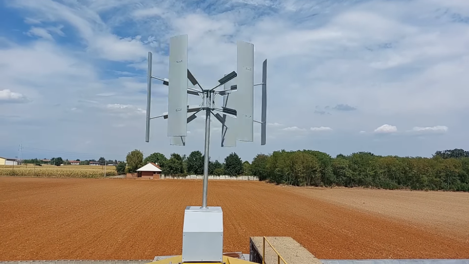
- Omnidirectional Wind Capture: VAWTs can capture wind from any direction without the need for yaw mechanisms or orientation towards the wind. This feature is particularly advantageous in urban or complex terrains where wind directions can be highly variable.
- Lower Wind Speed Operation: VAWTs are capable of operating in lower wind conditions. Their design allows them to start generating power at lower wind speeds, making them effective in areas where high wind speeds are not consistently available.
- Reduced Noise and Vibration: VAWTs tend to generate less noise and vibration compared to HAWTs. This characteristic makes them more suitable for residential areas or urban settings, where noise and vibration can be a concern.
- Ease of Maintenance: The main components of VAWTs often reside at ground level, making maintenance easier and less costly than HAWTs, where components typically mount higher on the tower.
- Space Efficiency: VAWTs have a smaller footprint relative to their height, which can make them more suitable for space-constrained environments such as urban areas. They can be installed closer together in wind farms, allowing for a more efficient use of land.
Common Materials
The evolution of materials used in wind turbine blades has paralleled technological advancements. Initially, materials such as wood and steel were common. However, the industry has shifted towards more advanced materials like fiberglass, carbon fiber, and composites. These materials offer an unmatched balance of strength, durability, and lightness, essential for efficient blade design.
Traditional Materials
Historically, wind turbine blades have been manufactured using materials such as fiberglass, known for its strength and durability. However, the weight of fiberglass limits the size and efficiency of the blades.
Advanced Materials
The introduction of advanced materials like carbon fiber composites has revolutionized blade design. These materials offer a higher strength-to-weight ratio, allowing for the construction of longer, more efficient blades. For instance, blades made from carbon fiber composites can be up to 20% lighter yet stronger than those made from traditional fiberglass, enabling an increase in blade length by up to 10-15% without a corresponding increase in weight. This extended blade length can significantly enhance the energy capture of wind turbines. Each meter of blade length produces up to 6-8% more energy, depending on specific wind conditions and turbine design.
Despite their higher cost, the benefits of using carbon fiber composites in turbine performance are substantial. The investment in these materials pays off through the increased efficiency and power output of the turbines. For example, a wind turbine utilizing blades made from advanced composites might produce 15-20% more electricity over its lifespan compared to a turbine with traditional materials, justifying the initial higher cost through improved energy generation and, potentially, reduced maintenance costs due to the material’s enhanced durability.
Sustainability
The sustainability of materials used in blade manufacturing is becoming increasingly important. The industry faces challenges in recycling old blades, prompting research into more sustainable materials and designs that are easier to recycle or repurpose at the end of their lifecycle.
Typical Lifespan
The lifespan of wind turbine blades can significantly impact the overall sustainability and cost-effectiveness of wind energy projects.
Average Lifespan
Wind turbine blades are designed to last between 20 to 25 years. The lifespan can be affected by the quality of the materials used, the precision of the blade design, environmental conditions, and maintenance practices employed.
Lifespan Influences
Factors such as rough weather conditions, operational stresses, and the quality of maintenance can all affect the longevity of a blade. Regular inspections and maintenance are crucial for maximizing blade life.
End-of-Life Options
The end-of-life disposal of wind turbine blades presents a challenge due to the durability and size of the materials. Efforts are underway to develop recycling methods that can handle the composite materials prevalent in blade construction, aiming to enhance the sustainability of wind energy further.
The efficiency of wind turbines is intricately linked to the design of their blades. By optimizing blade design for aerodynamic efficiency, employing advanced materials, and adhering to maintenance protocols, the energy output of wind turbines can be maximized. As the wind energy sector continues to evolve, ongoing research and innovation in blade design and materials science will play a critical role in the sustainable expansion of this vital renewable energy source.
![\[ %EL=\frac{final\, gauge\, length-initial\, gauge\, length}{initial\, gauge\, length}=\frac{l_{f}-l_{i}}{l_{i}}\times 100 \]](https://punchlistzero.com/wp-content/ql-cache/quicklatex.com-cc3c81206df19c01592732a21fdab98f_l3.png "Rendered by QuickLaTeX.com")
![\[ %RA=\frac{change\, in\, area}{original\, area}=\frac{A_{O}-A_{f}}{A_{O}}\times 100 \]](https://punchlistzero.com/wp-content/ql-cache/quicklatex.com-9e00dd3addd53aa4e937bec4bfb798f0_l3.png "Rendered by QuickLaTeX.com")
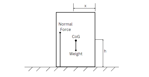
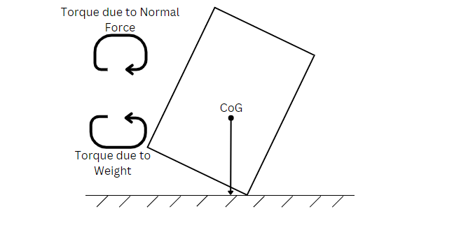
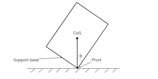
![\[ \theta =\tan^{-1}\left ( \frac{x}{h} \right ) \]](https://punchlistzero.com/wp-content/ql-cache/quicklatex.com-2fe971be0a742235bc60e761930be0b8_l3.png "Rendered by QuickLaTeX.com")

![\[ E_{line}=E_{phase} \]](https://punchlistzero.com/wp-content/ql-cache/quicklatex.com-daf81daccc773f6814376b13a4ad8152_l3.png "Rendered by QuickLaTeX.com")
![\[ E_{line}=E_{phase}\sqrt{3} \]](https://punchlistzero.com/wp-content/ql-cache/quicklatex.com-a455f695dc961638d32e5b30ade97cbd_l3.png "Rendered by QuickLaTeX.com")