Shop drawings, or fabrication drawings, provide fabrication details that a facility or field crew uses to manufacture a part or assembly. In this article, you will learn the definition of shop drawings, how shop drawings are used, examples, software, and alternatives.

Shop Drawing Definition
Shop drawings illustrate specific attributes and define exactly how a component should be manufactured. This helps the production process run smoothly. Shop drawings give welders and assemblers clarity, speed up the fabrication process, and reduce rework.
These detailed drawings typically hold little interest to the end customer and usually do not get submitted to a customer for review and commentary. Common shop drawings include weld maps, pipe spool drawings, and steel detailing drawings.
Shop drawings are considered engineering drawings, but due to their granular focus, they see a smaller distribution than more wildly distributed drawings such as general arrangement drawings, Piping and Instrumentation Diagrams (P&IDs), and Process Flow Diagram (PFDs)
How Shop Drawings are Used
For prefabricated components, shop drawings are usually necessary. Some of the details reflected on shop drawings are the following:
- Dimensions and specific instructions, that includes connection details, as required for manufacturing.
- Fabrication requirements
- Information about installation and construction
- Dimension that must be verified on-site
- Comparisons of construction documents for the architect or engineer to approve
- Notes on changes from the construction documents.
After a client approves assembly drawings, designers produce a package that includes shop drawings. Interested personnel such as fabricators, quality personnel, and plant managers review these drawings prior to shop issuance. Once printed and formally submitted to the shop floor, fitters, welders, and other skilled labor use shop drawings to understand manufacturing details.
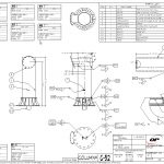
Shop Drawing Example
Shop drawings generally consist of weld maps, steel detailing drawings, pipe spool drawings, layout drawings, and welding logs.
Weld Map
- A Weld Map is a drawing design used to number each of the welds within it. The technique of numbering or marking each weld’s placement is what transforms the standard drawing into a map. Weld mapping refers to visible markings found on metal welded pieces.
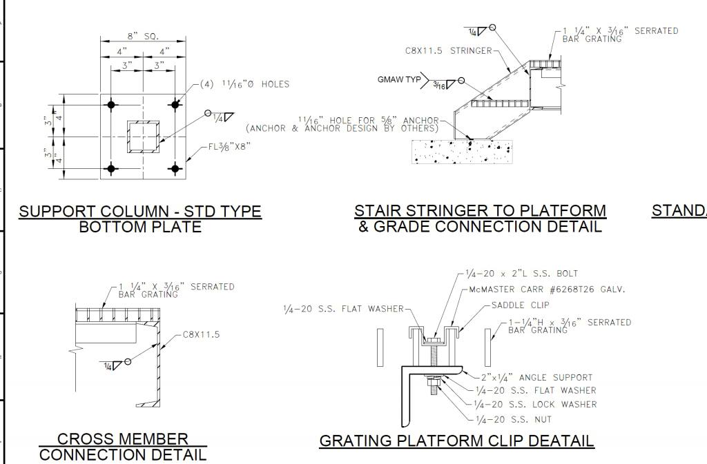
Steel Detailing Drawing
- Steel detailing drawings provide detail of how structural components fit together. This data typically includes cut lengths, saw angles, weld details, tolerances, and bolting details.
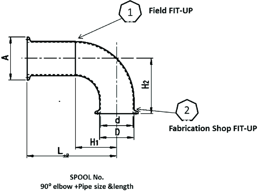
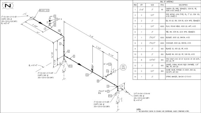
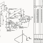
Pipe Spool Drawings
- Pipe spool drawings show the specific route that piping takes, weld details, and instrumentation connections. A pipe drawing’s principal aim is to present fabricators with a comprehensive view of each piece of pipe. Pipe spool drawings also provide easy readability for non-technical personnel.
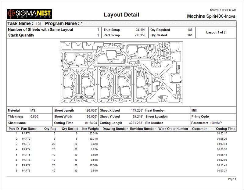
Layout Drawings
- Layout drawings optimize the use of steel during the production process. Most commonly, this applies to steel plates, but may involve steel beams and other items.
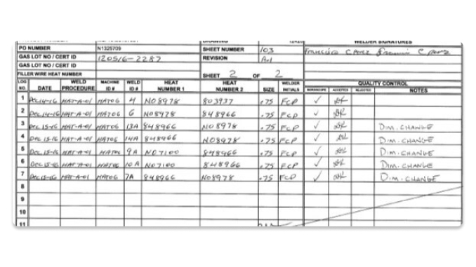
Welding Logs
- Welding logs conventionally do not categorize as a drawing, but provide important fabrication information associated with shop drawing production and use. They detail how welds apply to a particular component, the fabricator require.
Shop Drawing Software
The most common software used is Autocad. In most situations, engineers and designers create these drawings and deliver them to the shop via manually printed copies. As technology has improved, 3D modeling sees more frequent use.
Advantages of 3D Modeling
3D modeling provides an advantage of “build once, cut twice.” From a single model, a designer cuts different views of the assembly. This allows for ease in generating required drawings and drastically reduces the possibility of inconsistencies between high-level drawings and shop drawings. Common 3D packages include Creo, Solidworks, Advanced Steel, Revit, and Autocad 3D. Each of these packages offers different advantages depending on the application.
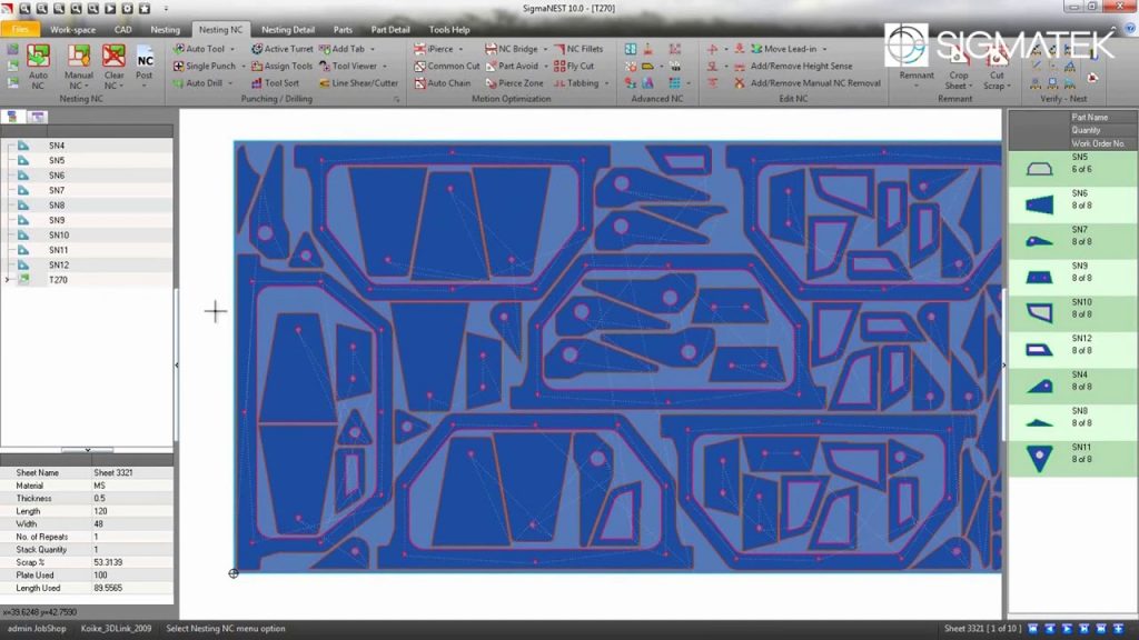
Nesting Software
Layout drawings of steel plates and beams allow for material optimization. This function occurs semi-automatically, with a designer importing a CAD file (typically .dxf type) into a program that automatically sorts and “nests” the files onto steel plates. Outputs from this file include a drawing and machine code. The machine code file then runs the CNC machine, plasma table, or laser cutting operation. This process may also be done with beams or any other process that requires material optimization.
Model Visualization
For shops that create 3D models, technology allows for the shop to explore the model thoroughly. This interaction allows for a fuller evaluation and understanding of design intent. It also allows for more in-depth quality inspection.
Model-Based Definition (MBD) for inspection, CMM-independent inspection plans, lean in-process inspection, and democratizing inspection are major trends helping to improve manufacturing productivity.
David Olson, Verisurf
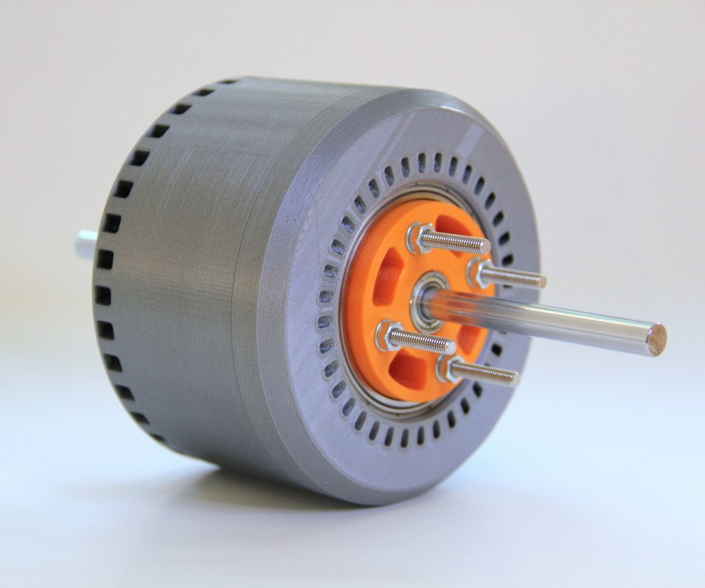
3D Printed Models
3D printed models allow for fabricators to understand build intent in a way that conventional engineering drawings may be unable to do. Generally, 3D printed models provide more value during the design phase than the build phase. However, 3D printed models may lend clarity for difficult to fabricate products.
Alternatives to Shop Drawings
Shop drawings apply to any fabricated component and convey a level of detail that general engineering drawings generaly don’t provide. From detailing weld placement to weld testing requirements, these drawings simplify the work of a fabricator and ensure the proper application of standards.
Nonetheless, several alternatives exist to the use of shop drawings by fabricators.
Working from General Arrangement Drawings
In some scenarios, general arrangement drawings may provide enough detail for fabricators to perform the required work. This arrangement makes sense for simple products that do not require detailed connector information.
Stick Building
“Stick-building” infers fabricating without the use of drawings. When the shop has a high degree of expertise, they may fabricate without the use of drawings. This type of fabrication also provides value for site installation scenarios where conditions cannot be determined prior to installation.
