Samuel
A weld map provides locations of welds on steel structures, pipe, pressure vessels, or specialty industrial equipment. In the fabrication of industrial material, locating different weld joints and seams allows for proper maintenance and supervision of systems and equipment under load.
Welds maps also provide documentation that fabrication has taken place on the equipment in question. Industrial-grade welds experience high loads and stress, thus tracking the weld location becomes important. Inspection and adherence to industrial weld standards are more easily upheld with the implementation of a weld map. In this article, you will learn the function of a map, map symbols, and mapping software options.
What is a Weld Map?

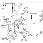
Weld maps allow for quick and easy inspection and identification of welds on a major piping system. A map includes the location of a weld, the configuration of the weld, whether it is a joint. Additionally, it includes joint configuration, and the original date of fabrication.
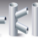
The main types of projects that benefit from a map are custom fabrication projects with varying thicknesses and connections. The welds are necessary to ensure proper connections between the varying sizes of piping. Being able to pinpoint the type of weld and location is essential.
Components
Weld mapping includes pictures and numbers to better identify the type of weld at a location. Thus, mapping welds also creates a means of weld identification that documents the completed work. Typically company requirements call for the specification and documentation of welds that are made on a major system. In order to comply with codes, regulations, and safety standards, weld mapping becomes especially useful.
Even if specifications and standards do not require the presence of a weld map, it often makes sense to create one for the general upkeep and maintenance of a piping system. There are many cases in which a weld fails and the system, being unmarked, makes it difficult for a company to better identify the location and means of repair on a system. Not knowing who or when a weld was last altered on a system makes it hard to repair a failed weld. Overall, for quality assurance and safety purposes, weld mapping provides strong insurance against any system assembly errors.
Weld Map Symbols
Notation communicates weld information and designation to those reading the plans.
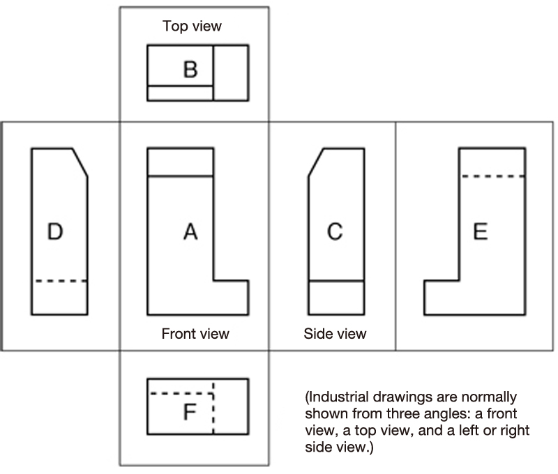
Typical standards follow the third angle standard of notation as it is of dominant use in the US.
Notation Example
On weld maps, the joints that a weld connects are useful as reference points for placing symbols on a map. We will discuss the main symbols and notations useful here.
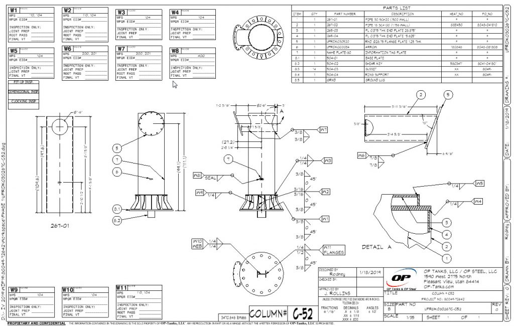
The reference line is useful in laying out vital information on the location in question of the system. It details the locations, dimensions, and other significant and supplemental information for any future adjustments. An arrow will typically be present on the weld to notate the location of the weld. The graphic below details many of the major components in the documentation on a weld map.
The weld symbol’s tail identifies the same information as a reference line. However, it will do so as it relates to the weld at that joint or location. The weld specs, initial fabrication date, and repair information will be in detail for proper documentation. The information will also include the process needed to repair the weld. The type of filler that was in use for the initial install is on the information section as well. Weld symbols are also useful for welders who wish to make structural repairs or adjustments to an existing weld.
Weld Mapping Software
Generally speaking, most fabrication shops receive and work with printed copies of weld maps. In recent years, weld mapping software has become more prevalent.
Depending on the application and accessibility map, there are a variety of different options available. Among the features present across the software are cloud capabilities for real-time adjustments and collaborations among groups.
Some platforms offer libraries to access standard specifications for weld requirements. The library helps to simplify the documentation process on a weld map. Other software provides add-ons to CAD and shop drawings, which offer a cheaper alternative to converting existing drawings and configurations of weld maps to more accessible and informational layouts.
Often, the welding software provides additional functionality by keeping track of welding procedures, welding procedure specifications (WPSes), and procedure qualification records (PQRs). Fabricators should carefully weigh the cost-benefit analysis of implementing additional functionality via software.